Liquid aeration plunger

a plunger and plunger technology, applied in the direction of fluid removal, positive displacement liquid engine, borehole/well accessories, etc., can solve the problems of plunger lift operating at a slowed rate, well to load-up, etc., to improve productivity, increase lift capacity and also lift velocity, and improve lift efficiency

Active Publication Date: 2009-04-07
PCS FERGUSON
View PDF44 Cites 38 Cited by
  • Summary
  • Abstract
  • Description
  • Claims
  • Application Information

AI Technical Summary

Benefits of technology

[0025]The present apparatus provides a plunger lift apparatus that can more effectively lift a heavy liquid. In short, a heavy liquid load can be brought to the surface at a higher rise velocity.
[0026]One or more internal orifices allow for a transfer of gas from the well bottom into the liquid load during plunger lift. This jetting of the gas causes an aeration to occur so the plunger may carry a heavy liquid load to the well top in an improved manner. In addition, a liquid load can rise at a higher velocity. The apparatus can increase the production of liquid allowing for a faster rise velocity with a fixed liquid load.
[0027]One aspect of the present invention is to provide a plunger apparatus that can have an extended capacity in carrying a liquid load to the well top.

Problems solved by technology

With the small tubing diameters, a relatively small amount of liquid may cause a well to load-up, or a relatively small amount of paraffin may plug the tubing.
In some cases, a large liquid loading can cause the plunger lift to operate at a slowed rate.

Method used


Image

  • Liquid aeration plunger
  • Liquid aeration plunger
  • Liquid aeration plunger

Examples


Embodiment Construction

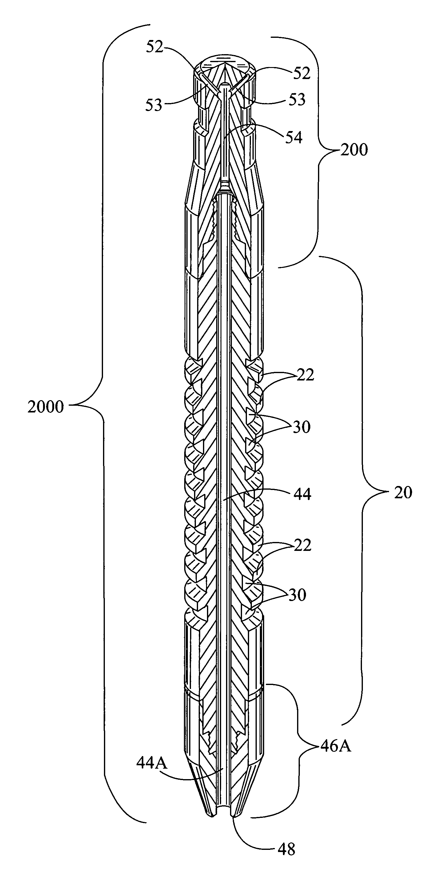
[0050]Referring now to the drawings, the present invention is a liquid aeration plunger 2000 apparatus (FIG. 5) having an upper section 200 (FIGS. 4,5) with an inner longitudinal orifice and one or more nozzle exit apertures at or near its upper end. The top section can comprise a standard American Petroleum Institute (API) fishing neck, if desired, but other designs are possible. The plunger has a mandrel mid section that can accommodate various sidewall geometries, an internal orifice throughout its length and a lower section 46A (FIG. 5) with an internal longitudinal orifice.

[0051]All the sections can be connected together to allow the gaseous aeration of the liquid load by the plunger of the present invention. When the surface valves open to start the lift process, gas is forced through the plunger nozzles. As the gas exits from the apertures into the liquid load, transferring momentum from the gas to the liquid, a turbulent and gaseous aeration of the liquid occurs. This action...


PUM


Abstract

A plunger apparatus operates to propel one or more jets of gas through one or more internal orifices and / or nozzles out through an aperture and into a liquid load whereby a transfer of the gas into the liquid load causes turbulent aeration to the liquid load during a plunger rise. This action can boost the carrying capacity of a plunger lift system resulting in improved well production.

Description

FIELD OF THE INVENTION[0001]The present invention relates to a plunger lift apparatus for the lifting of formation liquids in a hydrocarbon well. More specifically, the plunger comprises an internal nozzle apparatus that operates to propel one or more jets of gas through an internal aperture and into a liquid load, transferring gas into the liquid load and causing an aeration of the liquid load during lift.BACKGROUND OF THE INVENTION[0002]A plunger lift is an apparatus that is used to increase the productivity of oil and gas wells. Nearly all wells produce liquids. In the early stages of a well's life, liquid loading is usually not a problem. When rates are high, the well liquids are carried out of the well tubing by the high velocity gas. As a well declines, a critical velocity is reached below which the heavier liquids do not make it to the surface and start to fall back to the bottom, exerting back pressure on the formation and loading up the well. A plunger system is a method of...

Claims


Application Information

Patent Timeline
Patent Type & Authority Patents(United States)
IPC IPC(8): E21B34/14
CPCE21B43/121F04B47/12
Inventor VICTOR, BRUCE M.
Owner PCS FERGUSON
Why Eureka
Try Eureka