Cemented carbide inserts for earth-boring bits

a technology of cement carbide and inserts, which is applied in the direction of drill bits, earth-moving mining, drilling accessories, etc., can solve the problems of inability to insert, and inability to meet the requirements of drilling

Active Publication Date: 2009-04-07
KENNAMETAL INC
View PDF303 Cites 51 Cited by
  • Summary
  • Abstract
  • Description
  • Claims
  • Application Information

AI Technical Summary

Problems solved by technology

As rubbing action continues, considerable heat may be generated by the increase in friction, thereby resulting in the insert failing by thermal cracking and subsequent breakage.
Hence, the drill bit designer is invariably forced to compromise between failure occurring by wear of the dome and failure occurring by breakage of the cutting insert.
In addition, the cost of inserts used for earth-boring applications is relatively high since only virgin grades of cemented hard particles are employed for fabricating cutting inserts for earth-boring bits.

Method used


Image

  • Cemented carbide inserts for earth-boring bits
  • Cemented carbide inserts for earth-boring bits
  • Cemented carbide inserts for earth-boring bits

Examples


example 1

[0050]FIG. 3(a) shows an embodiment of a cutting insert 30 of the present invention having a cutting zone 31 comprising a cemented carbide grade having a Co content of 10 weigh percent and an average WC grain size of 0.8μm. The cutting zone 31 has a hardness of 92.0 HRA. The second zone, the body zone 32, comprises a cemented carbide grade having a Co content of 10 weigh percent and an average WC grain size of 3.0 μm. The body zone 32 has a hardness of 89.0 HRA. FIGS. 3(b)-3(d) illustrate the microstructures of the cutting zone (FIG. 3(b)), the transition zone between the cutting zone 31 and the body zone 32 (FIG. 3(c)), and the body zone 32(FIG. 3(d)), respectively. FIG. 3(e) illustrates the exterior of the insert.

[0051]The insert of example 1 was fabricated by filling a portion of the dome of the lower punch with the first cemented carbide powder corresponding to the cutting zone, followed by raising the die table and filling the mold with powder grade corresponding to the body zo...

example 2

[0052]FIG. 4(a) shows an embodiment of a cutting insert 41 of the present invention having a cutting zone 41 comprising a cemented grade having a Co content of 6 weigh percent and an average WC grain size of 1.5μm. The resultant cutting zone 41 has a hardness of 92.0 HRA. The body zone 42 comprises a cemented carbide grade having a Co content of 10 weigh percent and an average WC grain size of 3.0 μm. The body zone has a hardness of 89.0 HRA. FIGS. 4(b)-4(d) illustrate the microstructures of the cutting zone 41 (FIG. 4(b)), the transition zone between the cutting zone 41 and the body zone 42 (FIG. 4(c)), and the body zone 42 respectively. FIG. 4(e) illustrates the exterior of the insert.

[0053]The fabrication method employed for the inserts of example 2 was similar to the one employed for example 6.

example 3

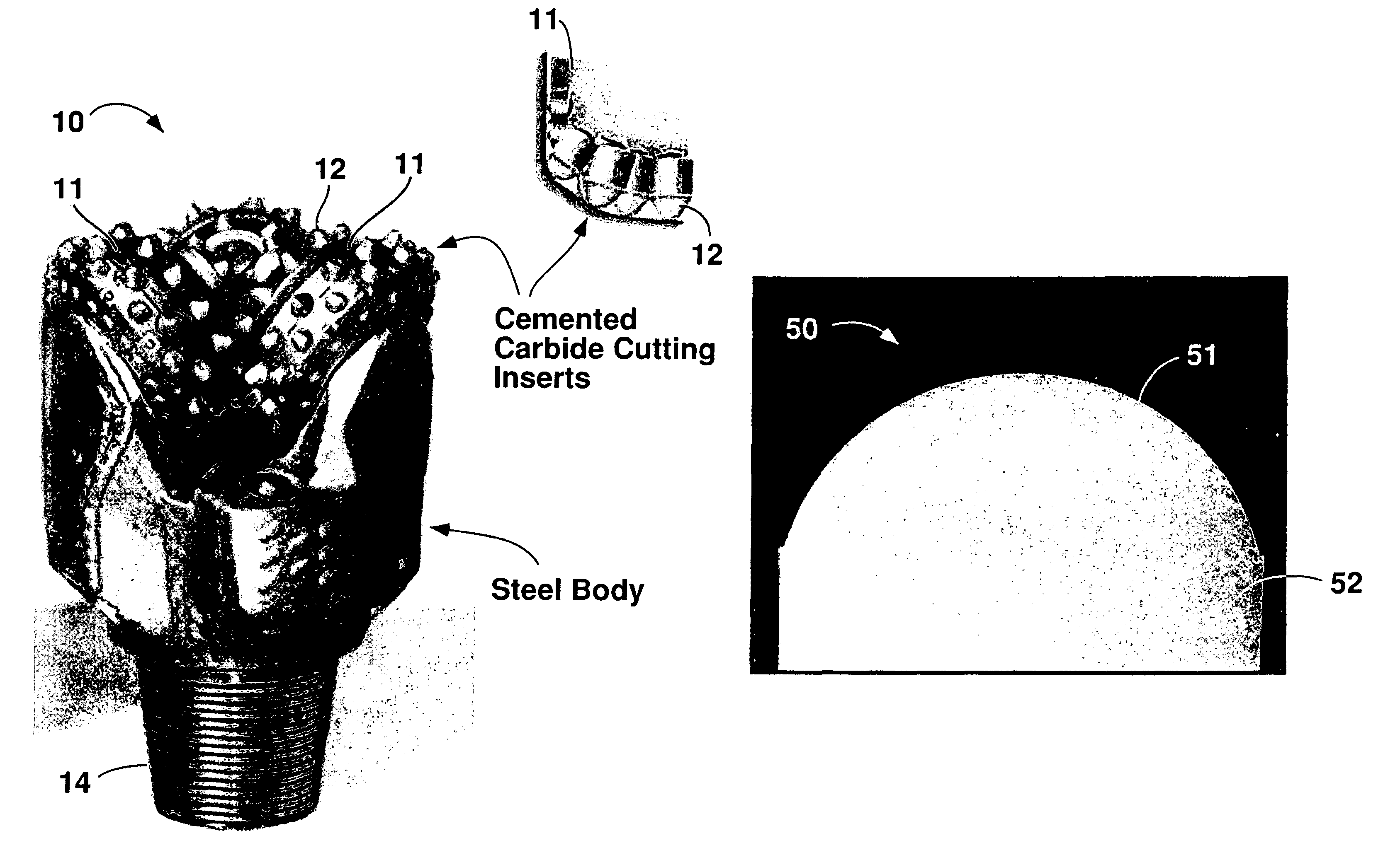
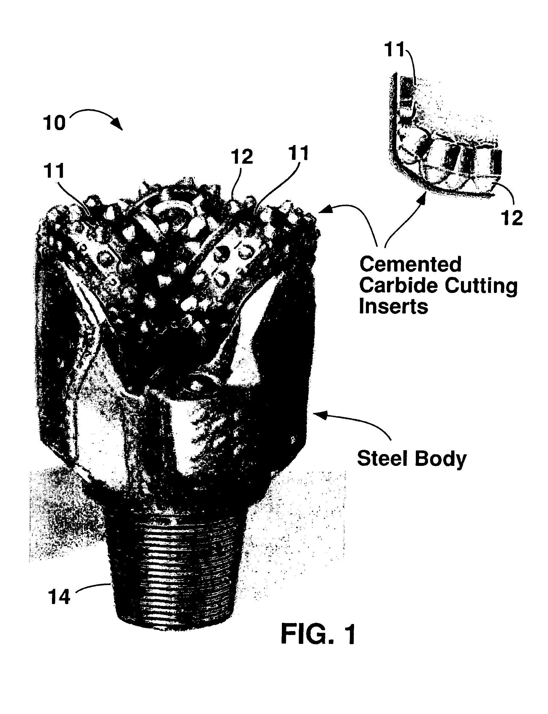
[0054]FIG. 5(a) shows an embodiment of an insert 50 having a cutting zone 51 based on a hybrid cemented carbide grade consisting of a mixture of two cemented carbide grades. The discontinuous phase with the cutting zone 51 is a first grade comprises 35 weigh percent of the cutting zone 51, and is a cemented carbide grade having a Co content of 10 weigh percent, an average grain size of 0.8 μm, and a hardness of 92.0 HRA. The continuous phase second grade of the hybrid cemented carbide comprises the remaining 65 weigh percent of the cutting zone 51 and is a cemented carbide grade having a Co content of 10 weigh percent, an average WC grain size of 3.0 μm, and a hardness of 89.0 HRA.

[0055]The body zone 52 of the cutting insert 50 of FIG. 5(a) comprises a cemented carbide grade having a Co content of 10 weigh percent and an average WC grain size of 3.0 μm. The resultant body zone 52 has a hardness of 89.0 HRA. FIGS. 5(b)-5(d) illustrate the microstructures of the cutting zone (FIG. 5(b...


PUM

PropertyMeasurementUnit
volume fractionaaaaaaaaaa
weight percentaaaaaaaaaa

Abstract

This invention relates to cutting inserts for earth boring bits comprising a cutting zone, wherein the cutting zone comprises first cemented hard particles and a body zone, wherein the body zone comprises second cemented hard particles. The first cemented hard particles may differ in at least one property from the second cemented hard particles. As used herein, the cemented hard particles means a material comprising hard particles in a binder. The hard particles may be at least one of a carbide, a nitride, a boride, a silicide, an oxide, and solid solutions thereof and the binder may be at least one metal selected from cobalt, nickel, iron and alloys of cobalt, nickel or iron.

Description

FIELD OF TECHNOLOGY[0001]This invention relates to improvements to cutting inserts and cutting elements for earth-boring bits and methods of producing cutting inserts for earth-boring bits. More specifically, the invention relates to cemented hard particle cutting inserts for earth-boring bits comprising at least two regions of cemented hard particles and methods of making such cutting inserts.BACKGROUND OF THE INVENTION[0002]Earth-boring (or drilling) bits are commonly employed for oil and natural gas exploration, mining and excavation. Such earth-boring bits may have fixed or rotatable cutting elements. FIG. 1 illustrates a typical rotary cone earth-boring bit 10 with rotatable cutting elements 11. Cutting inserts 12, typically made from a cemented carbide, are placed in pockets fabricated on the outer surface of the cutting elements 11. Several cutting inserts 12 may be fixed to the rotatable cutting elements 11 in predetermined positions to optimize cutting.[0003]The service lif...

Claims


Application Information

Patent Timeline
Patent Type & Authority Patents(United States)
IPC IPC(8): E21B10/00
CPCB22F7/06E21B10/52C22C29/005C22C29/067B22F2005/001B22F2998/00
Inventor MIRCHANDANI, PRAKASH K.MOSCO, ALFRED J.
Owner KENNAMETAL INC
Why Eureka
Try Eureka