Method and apparatus for electrostatic pickup for stringed musical instruments

a musical instrument and electrostatic pickup technology, applied in the field of musical instrument electrostatic pickup methods and instruments, can solve the problems of feedback squeal, microphone amplitude, and none fully addressed the unique requirements of acoustic stringed musical instruments, so as to prevent sudden electrostatic discharge, stop the crackling noise, and eliminate unwanted hum and nois

Inactive Publication Date: 2009-04-07
SNYDER JOHN JEROME
View PDF72 Cites 15 Cited by
  • Summary
  • Abstract
  • Description
  • Claims
  • Application Information

AI Technical Summary

Benefits of technology

[0028]An innovation of the electrostatic pickup assembly of this invention is a second plate placed inside the pickup assembly behind the pickup plate on the side away from the strings. This second plate is at electrical ground potential and shields the back of the pickup plate from any stray electrical fields, including any that may be picked up by the player's body acting as an antenna. The strings, also at ground potential, shield the front or string side of the pickup plate. This arrangement places the pickup plate between the grounded strings and the grounded back plate. This is very effective in eliminating unwanted hum and noise in electrically noisy environments, such as in the proximity of electronic digital devices like electronic keyboards, electric musical instruments, audio equipment, personal computers, displays, printers, modems, power supplies, etc. In addition, all wiring and connectors are electrically shielded, as is common practice for instrument pickups.
[0029]Another innovation is that the pickup and ground plates are enclosed in and separated by material(s) with a high dielectric constant, such as wood or plastic. The dielectric covering must be thick enough to prevent sudden electrostatic discharge when a player or object in any way touches the pickup plate assembly, either accidentally or intentionally. Any sudden uncontrolled discharge, caused by player contact with an unprotected pickup plate, may impart an unpleasant electrical shock to the player (akin to touching a doorknob after walking on a carpet during low-humidity winter weather). In addition, the uncontrolled electrostatic discharge may impose unwanted crackling noise on the output signal of the coupling capacitor, sending potentially damaging noise signals to connected audio equipment and speakers, which can be most unpleasant to hear. Simply painting the pickup plate is not sufficient to stop the crackling noise if the pickup plate is contacted; however, enclosing the plate with a thin layer of suitable dielectric material is an effective and reliable preventative. The dielectric covering increases the total effective air gap between pickup plate and strings (proportional to the material's dielectric constant and thickness), which helps reduce any variation in string height relative to the pickup plate. Similarly, the high dielectric material between the pickup plate and the ground plate on the back is equivalent to a much larger air gap between the pickup plate and the ground plate, which greatly reduces attenuation of the signal generated on the pickup plate by vibrating strings.

Problems solved by technology

Yet none have fully addressed the unique requirements for acoustic stringed musical instruments, such as guitars, dulcimers, harps, zithers, harpsichords, pianos, and other stringed musical instruments.
Difficulties in using microphones to amplify acoustic string instruments, particularly in live stage settings, have long been recognized by those skilled in the art.
In addition, particularly for live performances, great care must be taken in amplifier adjustments and in the placement of loud speaker(s) in order to avoid acoustic feedback, caused when some resonant sound(s) generated by the loud speaker(s) feeds back to the microphone at a resonant frequency or frequencies, greatly reinforcing itself each time the sound is picked up by the microphone and amplified again on its way back to the loud speaker, causing the all-too-familiar feedback squeal, which can be damaging to equipment and painful to hear.
Use of electromagnetic pickups necessitates the use of strings made with ferrous or ferrous-like alloys (such as nickel or phosphor bronze), to enable string vibrations to induce an electric current in the pickup coil, making electromagnetic pickups unsuitable for acoustic instruments using non-ferrous strings such as silver or nylon.
e). However, the development of electrostatic pickups largely neglected the unique requirements for acoustic stringed musical instruments and has received little attention in recent ye
The pick guard above the fret-board strings limited the area in which the pick could be used, somewhat altering the position of the player's hand.
In spite of the pick guard and paint covering the plates, occasional accidental contact of a player's fingers or pick with a pickup plate would impart an unpleasant electrical shock to the player (akin to touching a doorknob after walking on a carpet during low-humidity winter weather).
In addition, sudden uncontrolled electrostatic discharge created sudden intense crackling noise on the output signal of the DC blocking capacitor, sending potentially damaging noise pulses to connected equipment and speakers, which listeners would experience as loud, sharp, crackling noise.
There are two other issues with the prior art of electrostatic capacitive pickups for stringed instruments, including Gebhardt's embodiment.
First, mounting the pickup plate(s) required attaching each plate with at least three screws penetrating into the body or structure of the instrument.
In at least one case, some players felt that the long pickup plate on a zither under the accompaniment strings physically muted the sound of an instrument, weakening its tone.
The permanent nature of the pickup plate mounting made their removal difficult, discouraging unimpaired use of an instrument either with or without its pickup(s) at player discretion.
Another issue is the need for a high-voltage electric charge for the pickup plate, typically over 240 volts DC.
However, as transistor radios became popular, portable tube radios and their high-voltage batteries became harder to obtain, eventually becoming obsolete.

Method used


Image

  • Method and apparatus for electrostatic pickup for stringed musical instruments
  • Method and apparatus for electrostatic pickup for stringed musical instruments
  • Method and apparatus for electrostatic pickup for stringed musical instruments

Examples


Embodiment Construction

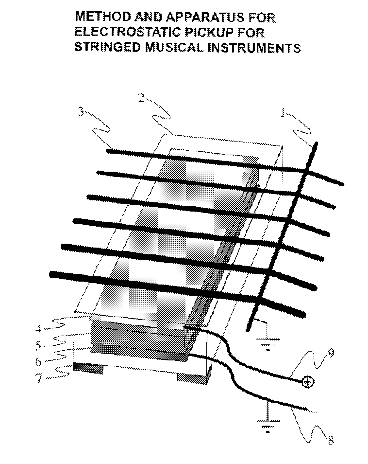
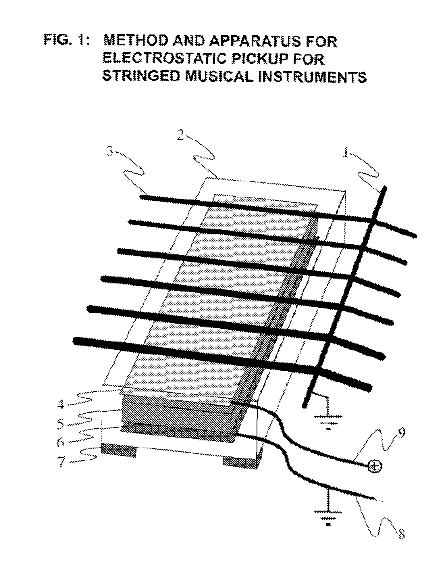
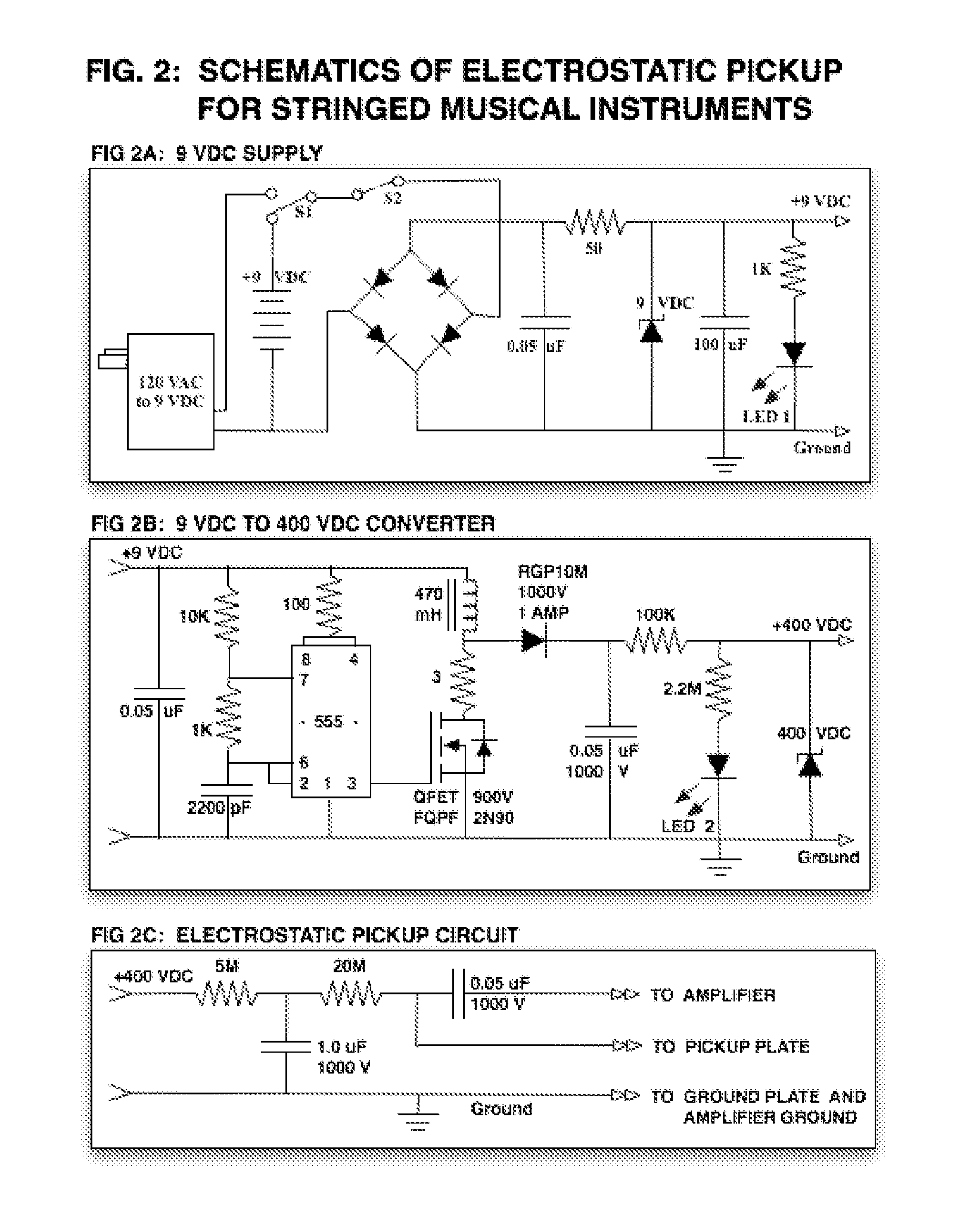
[0047]Refer to the drawings, in which numbers refer to indicated elements and electronic components are depicted using standard electronic symbols with stated component values. All resistance values are in ohms.

[0048]FIG. 1 shows an electrostatic pickup assembly pointed to by number 2. The illustration is not to scale, but illustrates the relative positions of various components. The outer surfaces of pickup assembly 2 consist of a high dielectric material such as wood or plastic. The pickup is placed in proximity to one or more musical instrument strings 3, strung over a bridge 1. In this illustration the bridge 1 incorporates a metal wire that touches the strings 3, which is used to keep the strings at electrostatic ground potential. In practice, other means may be used to provide the strings with contact to an electric ground. Inside the pickup assembly 2 are two metal plates, the pickup plate 4 and a ground plate 6, which are separated by material 5 with a high dielectric consta...


PUM


Abstract

This invention relates to the method and apparatus for electrostatic pickup of sound from stringed musical instruments to addresses the unique requirements of acoustic stringed musical instruments with a portable, detachable, safe-to-handle, easy-to-use, low-noise, electrostatic pickup that captures the tone of the musical instrument, is usable with common musical sound systems, avoids acoustic feedback problems associated with air microphones in live settings, and is easy to manufacture using current common materials and practices.

Description

TECHNICAL FIELD AND INDUSTRIAL APPLICABILITY OF THE INVENTION[0001]This invention relates to the method and apparatus for electrostatic pickup of sound for stringed musical instruments and their manufacture. The present invention addresses the unique requirements of acoustic stringed musical instruments with a portable, detachable, safe-to-handle, easy-to-use, low-noise, electrostatic pickup that captures the tone of the musical instrument, is usable with common musical sound systems, avoids acoustic feedback problems associated with air microphones in live settings, and is easy to manufacture using current common materials and practices.BACKGROUND OF THE INVENTION[0002]Those skilled in the art know the long history of development of microphones and pickups for musical instruments. Yet none have fully addressed the unique requirements for acoustic stringed musical instruments, such as guitars, dulcimers, harps, zithers, harpsichords, pianos, and other stringed musical instruments.[0...

Claims


Application Information

Patent Timeline
Patent Type & Authority Patents(United States)
IPC IPC(8): G10H3/18
CPCG10H3/181G10H2220/565
Inventor SNYDER, JOHN JEROME
Owner SNYDER JOHN JEROME
Why Eureka
Try Eureka