
Structure and access method for magnetic memory cell and circuit of magnetic memory

a magnetic memory and structure access technology, applied in the field of magnetic memory technology, can solve the problems of large magnetic field unsuitability, single-layer magnetic free layer writing error, and low writing current, and achieve the effect of simple operation procedure, increased operating rate and low writing curren

Inactive Publication Date: 2009-04-07
IND TECH RES INST
View PDF4 Cites 41 Cited by
  • Summary
  • Abstract
  • Description
  • Claims
  • Application Information

AI Technical Summary

Benefits of technology

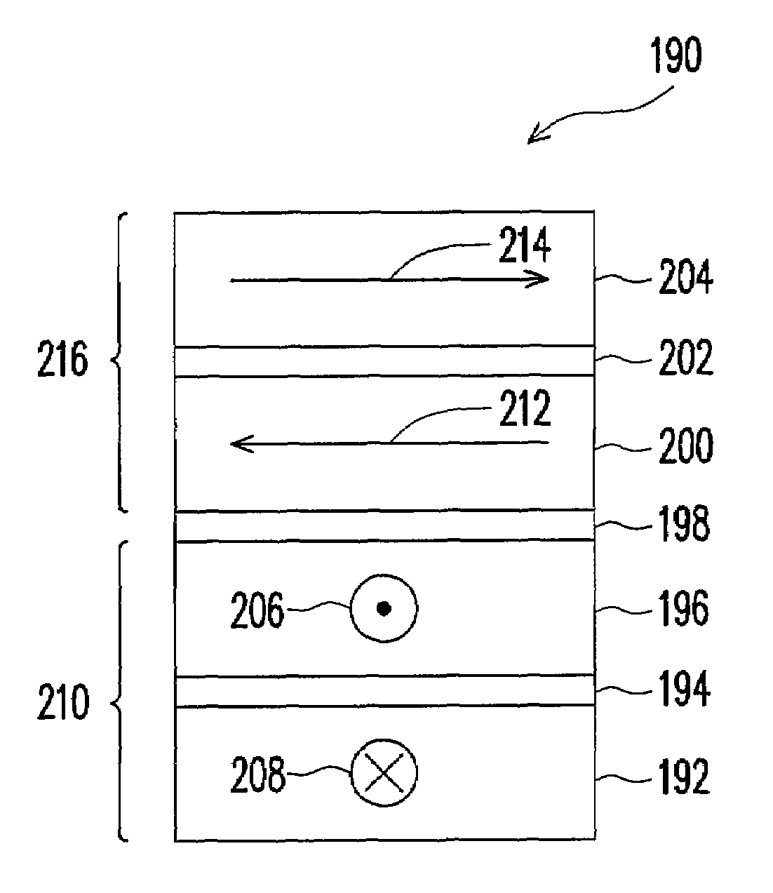
The present invention provides a magnetic memory cell structure with low writing current and simple operation procedure, which increases operating rate. The structure includes a stacked magnetic pinned layer with a top pinned layer and a bottom pinned layer, and a tunnel barrier layer disposed on the stacked magnetic pinned layer. A magnetic bias layer is optionally included to shift the writing operation area to a magnetic field zero. The data access method includes a data access reading method and a data access writing method, which provide efficient data access for a magnetic memory device.

Problems solved by technology

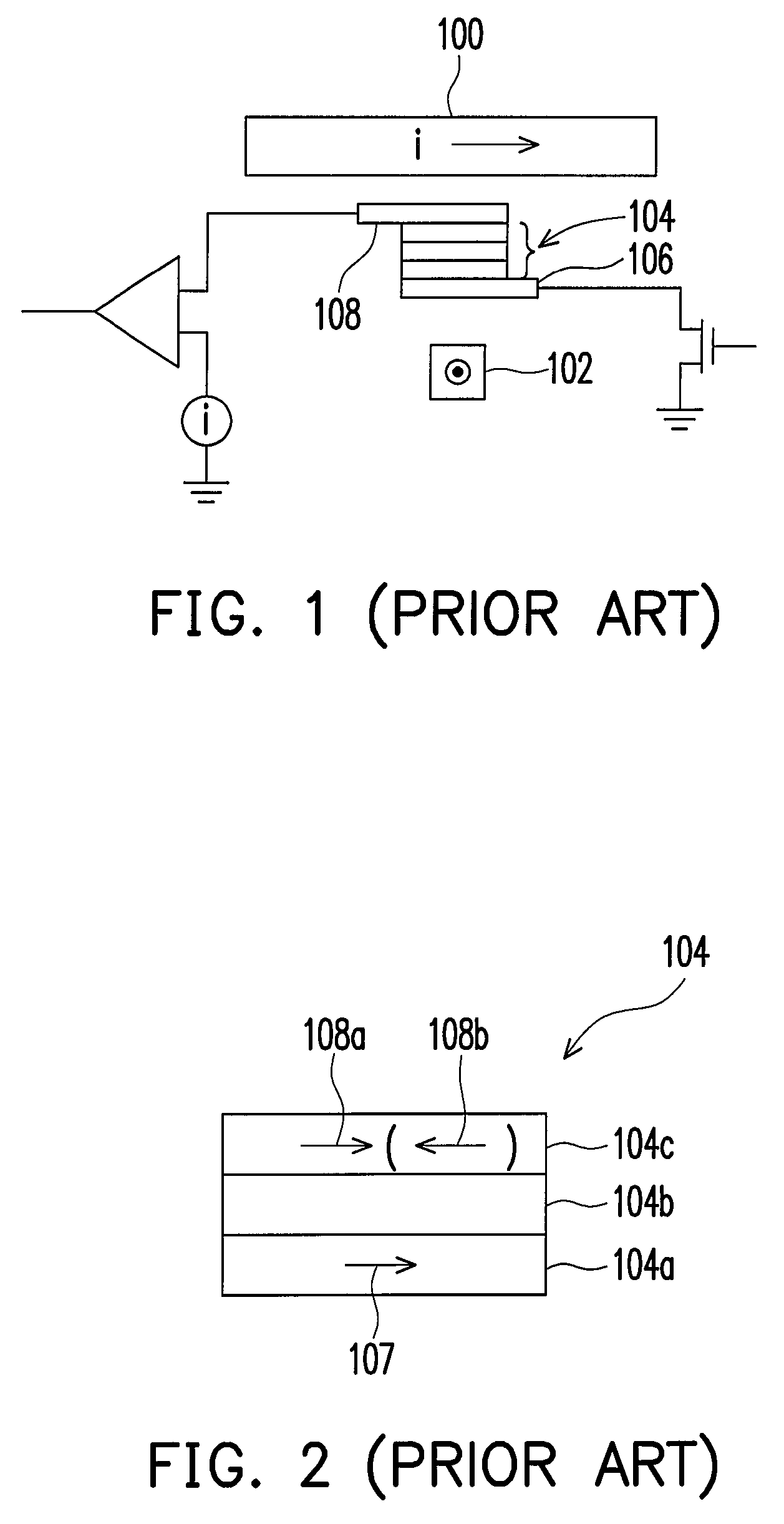
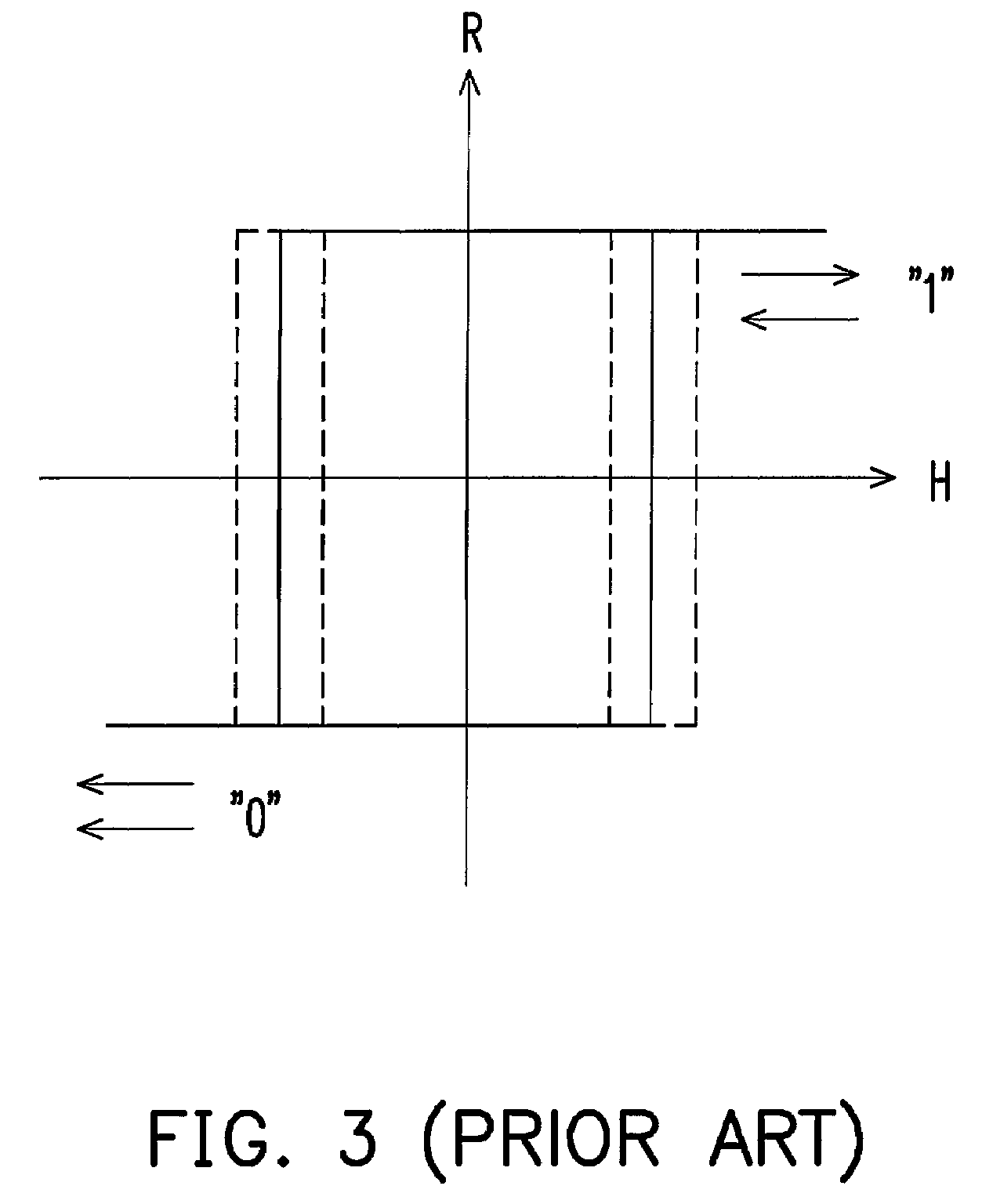
However, the magnetic memory device includes a plurality of memory cells, and the condition of each memory cell is different, thus, the magnetoresistance curve may have variations as shown by the dashed line, which may result in writing error. FIG. 4 illustrates the array structure of conventional memory cells.
Large magnetic fields are not suitable because the adjacent memory cells will be disturbed magnetically if the magnetic fields are too large.
Thus, writing error may be caused to the single-layer magnetic free layer 104c in FIG. 2.
Thus, the conventional technologies described above may cause data errors.
The read before write process may cause at least slow operation rate, and the common reference bits may result in the reference memory cell being overloaded, which may affect the operation rate and also damages to the reference memory cell.

Method used


Image

  • Structure and access method for magnetic memory cell and circuit of magnetic memory
  • Structure and access method for magnetic memory cell and circuit of magnetic memory
  • Structure and access method for magnetic memory cell and circuit of magnetic memory

Examples


Embodiment Construction

[0059]The present invention provides a magnetic memory cell structure which allows at least lower writing current to increase the operation yield. Besides, the present invention also provides a data access method. Based on the magnetic memory cell structure and the data access method, the present invention can effectively reverse the direction of the magnetization vector of the magnetic free layer, and further more can reduce data writing errors through negative current pulse. Moreover, the present invention also provides a magnetic memory circuit which employs the aforementioned magnetic memory cell structure and data access method and can distract the load of a reference memory cell. The present invention will be described with reference to some embodiments in following, however, the present invention is not limited to these embodiments.

[0060]FIG. 8 is a cross-sectional view schematically illustrating the structure of a magnetic memory cell according to an embodiment of the presen...


PUM


Abstract

A magnetic memory cell, used in a magnetic memory device, includes a stacked magnetic pinned layer, serving as a part of the base structure. The stacked magnetic pinned stacked layer has a top pinned layer and a bottom pinned layer, between which there is a sufficient large magnetic coupling force to maintain magnetization of the top pinned layer on a reference direction. A tunnel barrier layer is disposed on the stacked magnetic pinned layer. A magnetic free stacked layer is disposed on the tunnel barrier layer. The magnetic free stacked layer includes a bottom free layer having a bottom magnetization and a top free layer having a top magnetization. When no assisted magnetic field is applied, the bottom magnetization is anti-parallel to the top magnetization and is perpendicular to the reference direction on the top pinned layer. A magnetic bias layer can be also disposed on the top free layer.

Description

CROSS-REFERENCE TO RELATED APPLICATION[0001]This application claims the priority benefit of Taiwan application serial no. 95113731, filed on Apr. 18, 2006. All disclosure of the Taiwan application is incorporated herein by reference.BACKGROUND OF THE INVENTION[0002]1. Field of the Invention[0003]The present invention relates to technology of a magnetic memory. More particularly, the present invention relates to the structure and access method for a magnetic memory cell and the circuit of a magnetic memory, wherein it at least has the properties of low writing current and using an adjacent memory cell as a reference memory cell.[0004]2. Description of Related Art[0005]Magnetic memory, for example, magnetic random access memory (MRAM), is also a non-volatile memory, which has such advantages as non-volatility, high density, high read / write rate, anti-radiation etc. Magnetic memory records data of logic “0” or logic “1” through the magnetoresistance produced by parallel or anti-paralle...

Claims


Application Information

Patent Timeline
Patent Type & Authority Patents(United States)
IPC IPC(8): G11C11/00
CPCG11C11/16
Inventor HUNG, CHIEN-CHUNGCHEN, YUNG-HSIANGKAO, MING-JERLEE, YUAN-JENWANG, YUNG-HUNG
Owner IND TECH RES INST
Learn More