
Coherent terahertz radiation source

a radiation source and coherent technology, applied in the field of coherent terahertz radiation sources, can solve the problems of high thz loss, low power output, and strong thz absorption in the thz regime, and achieve the effect of low thz loss and high power outpu

Active Publication Date: 2009-04-07
WISCONSIN ALUMNI RES FOUND
View PDF3 Cites 38 Cited by
  • Summary
  • Abstract
  • Description
  • Claims
  • Application Information

AI Technical Summary

Benefits of technology

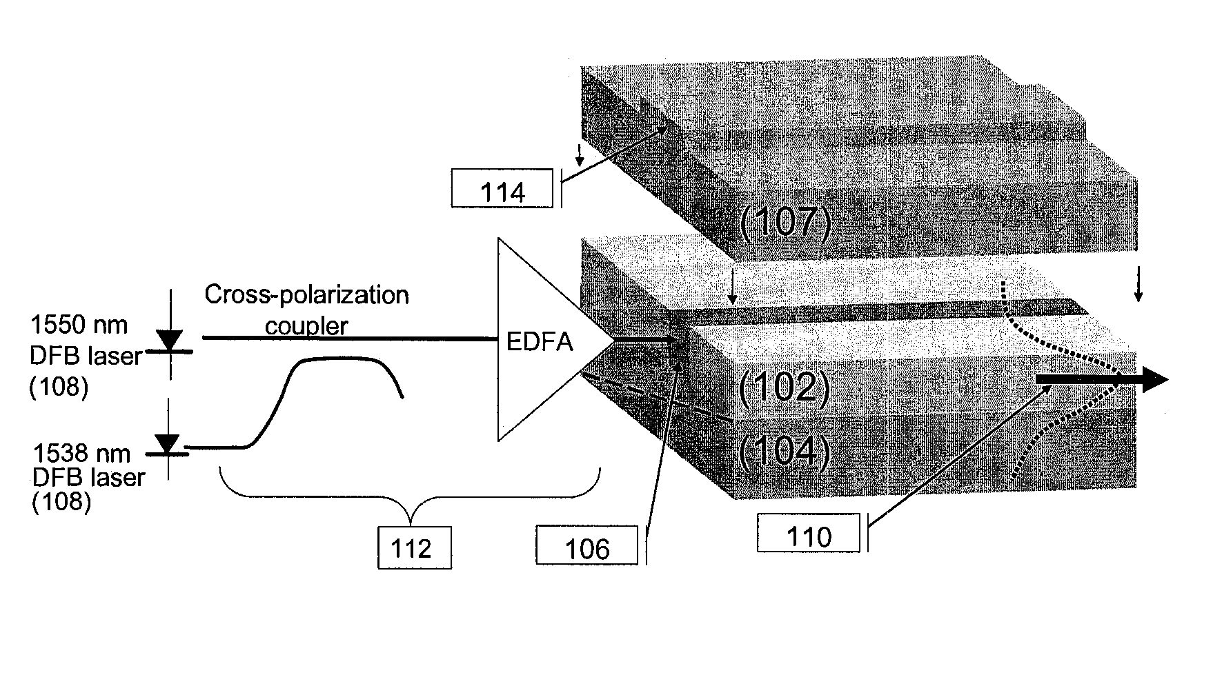
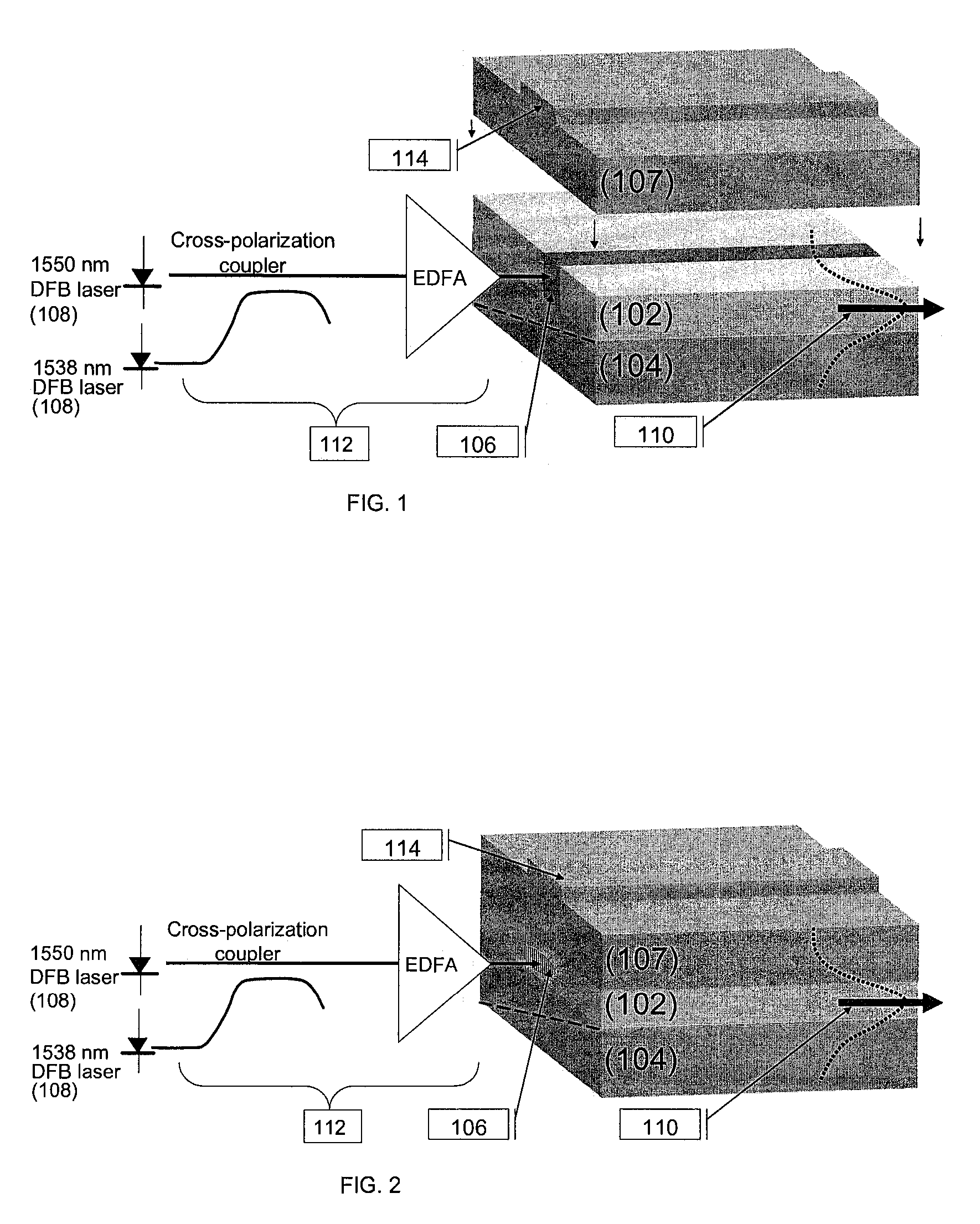
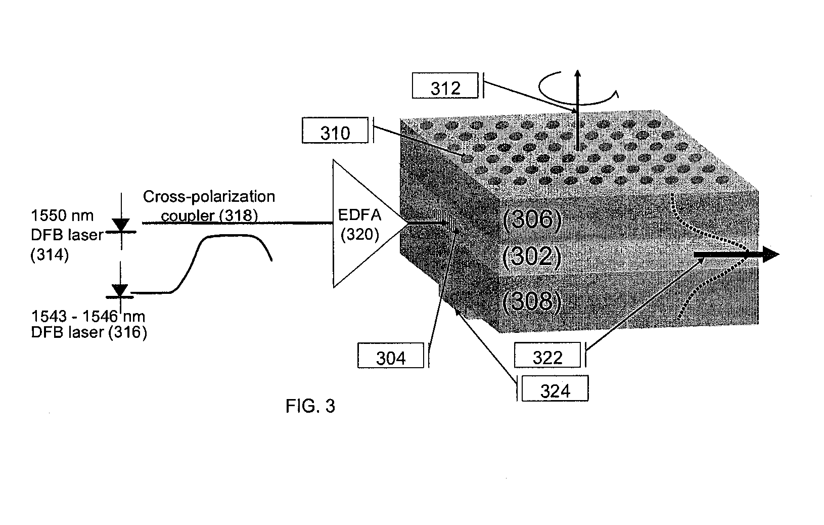
[0005]This invention provides a THz radiation source comprising a dual waveguide heterostructure. The dual waveguide heterostructure includes an optical waveguide contained within a larger THz waveguide layered structure. The radiation source provides a coherent guided wave of THz radiation which is generated via difference frequency mixing in a gain medium with a large second-order nonlinearity and propagated with low THz loss by a dielectric medium in the layered waveguide structure. The THz radiation source is compact, has a high power output, and may be operated either in continuous-wave (CW) or pulsed mode at room temperature.
[0007]A guided wave of THz radiation may be generated by directing two guided optical pump beams at the proximal end of the optical channel waveguide to produce a guided THz beam via difference frequency mixing. Efficient difference frequency mixing requires that the two pump beams and the THz beam overlap strongly and are phase matched. In the present THz radiation sources, proper choice of the refractive indices and / or thicknesses of the dielectric cladding materials can be used to improve the optical field overlap of the optical pump beams and the THz product, as well as reducing phase mismatch. Phase matching may also be improved by use of periodic poling in the nonlinear optic material (i.e., periodically reversing the direction of the spontaneous polarization present in the nonlinear optic material.)

Problems solved by technology

Unfortunately, the lack of sufficiently powerful, compact sources and detectors in the 0.3 to 30 THz range has drastically limited the development of THz sources for use in these fields.
The major drawback of these materials is that, unpumped, they absorb strongly (α˜25 cm−1) in the THz regime.
As a consequence, conventional THz generation has been limited either to surface interactions by way of reflection or diffraction, or to bulk interactions through thin (˜1 mm thick) samples.

Method used


Image

  • Coherent terahertz radiation source
  • Coherent terahertz radiation source
  • Coherent terahertz radiation source

Examples


Embodiment Construction

[0013]The present invention provides a THz radiation source comprising a dual waveguide heterostructure that includes an optically pumped channel waveguide surrounded by a transparent THz waveguide. The THz waveguide in the dual waveguide heterostructure is a layered structure that includes a thin layer of nonlinear optic material sandwiched between cladding layers comprised of dielectric material. The optical waveguide in the dual waveguide heterostructure is a channel waveguide defined within the nonlinear optic layer.

[0014]The nonlinear optic material in the dual waveguide structure is a thin layer of material having a large inherent second-order nonlinearity. Although it is desirable to choose materials with a relatively low absorption in the THz frequency range, many materials that have large second-order nonlinearities tend to absorb in the THz frequency range. Fortunately, the present dual waveguide structure helps mitigate THz losses due to absorption in the gain medium, as ...


PUM


Abstract

A THz radiation source comprising a dual waveguide heterostructure is provided. The dual waveguide heterostructure includes an optical waveguide contained within a larger THz waveguide layered structure. The radiation source provides a coherent guided wave of THz radiation which is generated via difference frequency mixing in a gain medium with a large second-order nonlinearity and propagated with low THz loss by a dielectric medium in the layered waveguide structure. The THz radiation source is compact, has a high power output, and may be operated in continuous-wave (CW) mode at room temperature.

Description

STATEMENT OF GOVERNMENT RIGHTS[0001]This invention was made with United States government support awarded by the National Science Foundation (NSF) under grant numbers 0505775 and 0450509. The United States government has certain rights in this invention.FIELD OF THE INVENTION[0002]This invention pertains generally to coherent terahertz radiation sources. More specifically, this invention pertains to terahertz radiation sources having a dual waveguide structure that incorporates both an optical waveguide and a terahertz waveguide.BACKGROUND OF THE INVENTION[0003]Terahertz (THz) radiation is of great interest for imaging science and technology applications, with potentially great promise for homeland security, medical imaging, and defense imaging applications, among others. With their high sensitivity and selectivity, THz systems can be used to monitor public facilities, high-occupancy buildings, and even the open air for toxic industrial chemicals, chemical agents, biological agents,...

Claims


Application Information

Patent Timeline
Patent Type & Authority Patents(United States)
IPC IPC(8): G02B6/00
CPCG02F1/3534G02F1/365G02F2203/13
Inventor MCCAUGHAN, LEONSTAUS, CHADKUECH, THOMAS F.
Owner WISCONSIN ALUMNI RES FOUND
Learn More