
Server side API for fencing cluster hosts via export access rights

Active Publication Date: 2009-04-07
NETWORK APPLIANCE INC
View PDF32 Cites 45 Cited by
  • Summary
  • Abstract
  • Description
  • Claims
  • Application Information

AI Technical Summary

Benefits of technology

[0019]The host API message notifies the Server API of the storage system that a modification must be made in one of the export lists. This modification is to be made so that a target cluster member, for example, cannot write to any of the disks in the storage system, thereby fencing off that member from that data. For example, the Server API of the storage system receives the host API message from a cluster member that a particular target cluster member is to be fenced. The message is forwarded to the Export Module of the NFS server. The Server API instructs the Export Module to change the read-write access permission right of a particular cluster member to a read only access as to one or more given exports to fence that cluster member from certain exports. In other instances, read-write permission is restored in an unfencing operation. A single host API message can be used for all requests for a particular storage system identified with the same user name and password. As a result, the multiple requests can be combined for fencing and unfencing operations and these operations do not have to be performed separately.

Problems solved by technology

However, if both nodes are still in normal operating condition, the absent heartbeat signal may be the result of interconnect failure.
In addition, a node that is not properly functioning may need to have its access to the data of the storage system restricted.
Moreover, the NFS protocol does not support SCSI reservations, and thus prior techniques which relied on SCSI reservations would not be suitable for an environment in which access to the storage system is through NFS.
Thus, a network accessed storage system does not fit into this traditionally disk-based host cluster model.

Method used


Image

  • Server side API for fencing cluster hosts via export access rights
  • Server side API for fencing cluster hosts via export access rights
  • Server side API for fencing cluster hosts via export access rights

Examples


Embodiment Construction

A. Cluster Environment

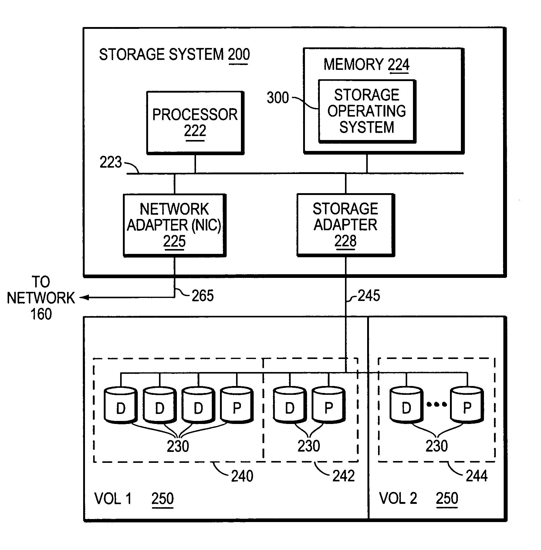
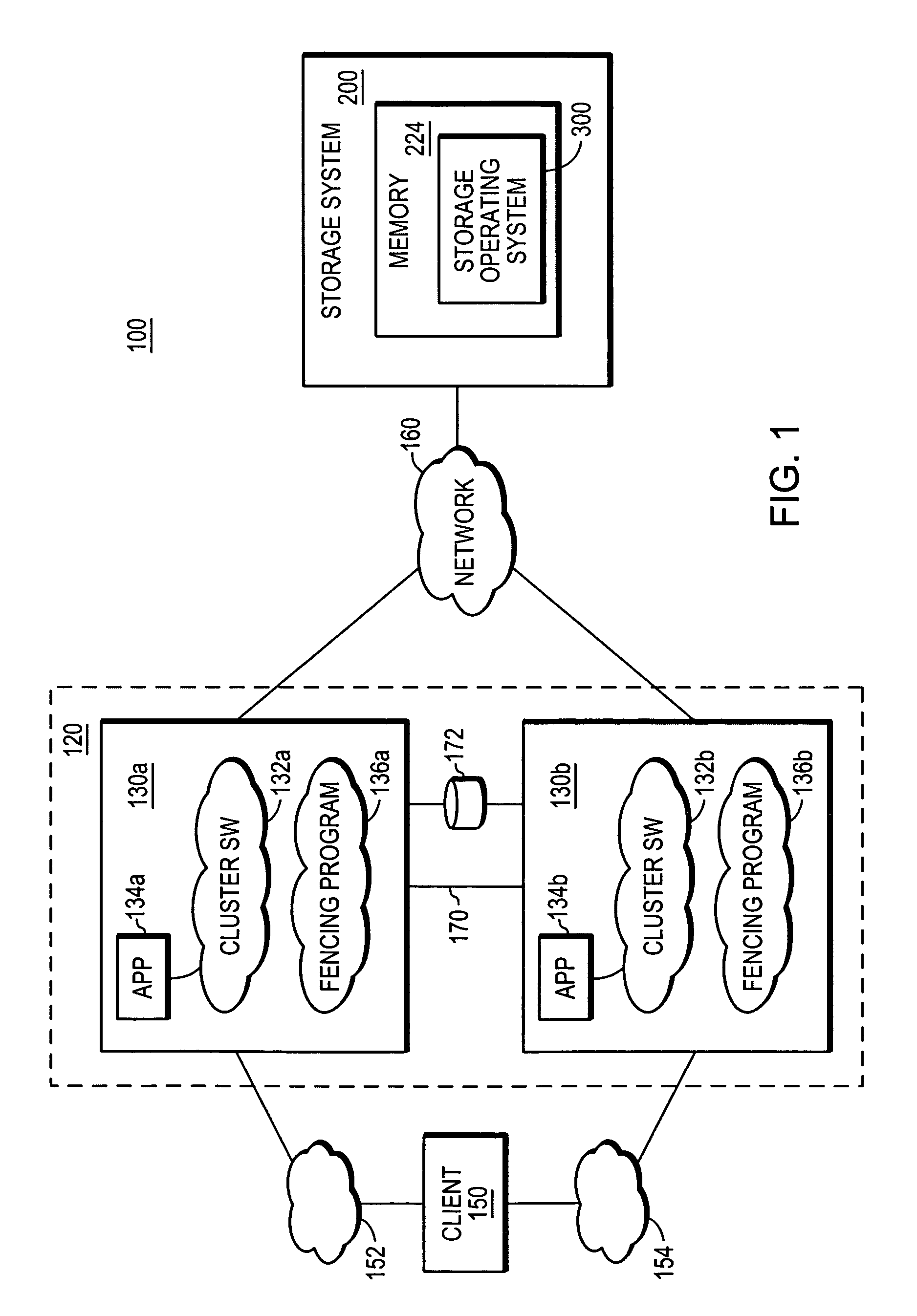
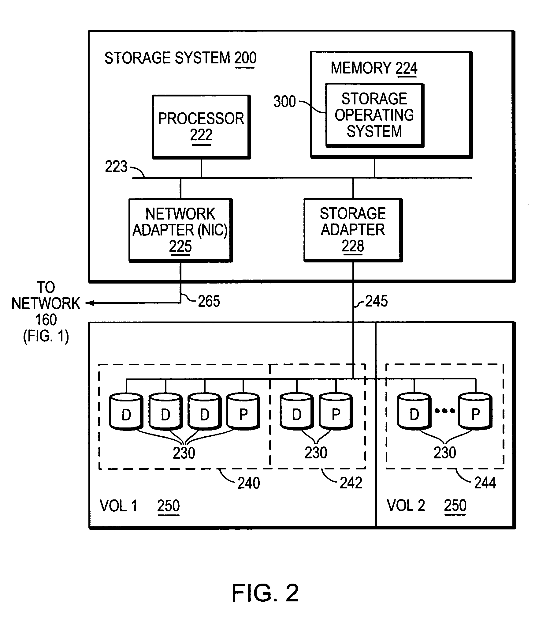
[0030]FIG. 1 is a schematic block diagram of a storage environment 100 that includes a cluster 120 having cluster members 130a and 130b, each of which is an identically configured redundant node that utilizes the storage services of an associated storage system 200. For purposes of clarity of illustration, the cluster 120 is depicted as a two-node cluster, however, the architecture of the environment 100 can vary from that shown while remaining within the scope of the present invention.

[0031]Cluster members 130a and 130b comprise various functional components that cooperate to provide data from storage devices of the storage system 200 to a client 150. The cluster member 130a includes a plurality of ports that couple the member to the client 150 over a computer network 152. Similarly, the cluster member 130b includes a plurality of ports that couple that member with the client 150 over a computer network 154. In addition, each cluster member 130, for example, h...


PUM


Abstract

A method and system performs fencing techniques in a host cluster storage environment. A fencing application program interface resides in one or more storage systems. When a message is received by said storage system from a cluster member, the storage system in turn modifies the NFS export lists of one or more storage systems to restrict further access by the failed cluster node to otherwise fence the failed cluster node off from that storage system or from certain directories within that storage system. Prior to said access permission rights being changed, NFS operations are locked and drained, NFS locks are removed after which the export lists are modified. Once the fencing operations are performed, the NFS operations are served again by the storage system.

Description

BACKGROUND OF THE INVENTION[0001]1. Field of the Invention[0002]This invention relates to data storage systems, and more particularly, to failure fencing in networked data storage systems.[0003]2. Background Information[0004]A storage system is a computer that provides storage service relating to the organization of information on writable persistent storage devices, such as memories, tapes or disks. The storage system is commonly deployed within a storage area network (SAN) or a networked storage environment. When used within a networked environment, the storage system may be embodied as a storage system including an operating system that implements a file system to logically organize the information as a hierarchical structure of directories and files on, e.g. the disks. Each “on-disk” file may be implemented as a set of data structures, e.g., disk blocks, configured to store information, such as the actual data for the file. A directory, on the other hand, may be implemented as a...

Claims


Application Information

Patent Timeline
IPC IPC(8): G06F12/12G06F12/14
CPCG06F17/30197G06F21/6218G06F21/80G06F2221/2119G06F2221/2141G06F16/1824
Inventor HAYNES, THOMASDANIEL, STEPHENRICHART, JOSEPHERASANI, PRANOOP
Owner NETWORK APPLIANCE INC
Learn More