Piston-type accumulator

a technology of accumulator and piston, which is applied in the direction of piston rings, fluid-pressure actuators, pipe elements, etc., can solve the problems of less suited applications for hydraulic or piston-type accumulators, considered heavy in weight, etc., and achieves the effect of short trigger times and little weight in us

Active Publication Date: 2009-04-14
HYDAC TECH GMBH
View PDF8 Cites 13 Cited by
  • Summary
  • Abstract
  • Description
  • Claims
  • Application Information

AI Technical Summary

Benefits of technology

[0005]An object of the present invention is to provide improved piston-type accumulators, while retaining the advantages of such conventional accumulators, such that short trigger times are possible with the separating piston and an accumulator with little weight in use is implemented.

Problems solved by technology

The separating piston formed of a steel material is large in its axial direction of motion within the accumulator housing, and can be considered heavy in terms of weight.
As a result of the associated sluggish dynamic behavior of the piston-like separating element, the known hydraulic or piston-type accumulator is less suited for applications in which the separating piston must be moved in a rapid sequence, for example, in the cases in which on the fluid side high-frequency pressure pulses are delivered into the accumulator, and for those cases in which the piston-type accumulator is supposed to entail less weight, for example, in the areas of aeronautics and astronautics.

Method used


Image

  • Piston-type accumulator
  • Piston-type accumulator
  • Piston-type accumulator

Examples


Embodiment Construction

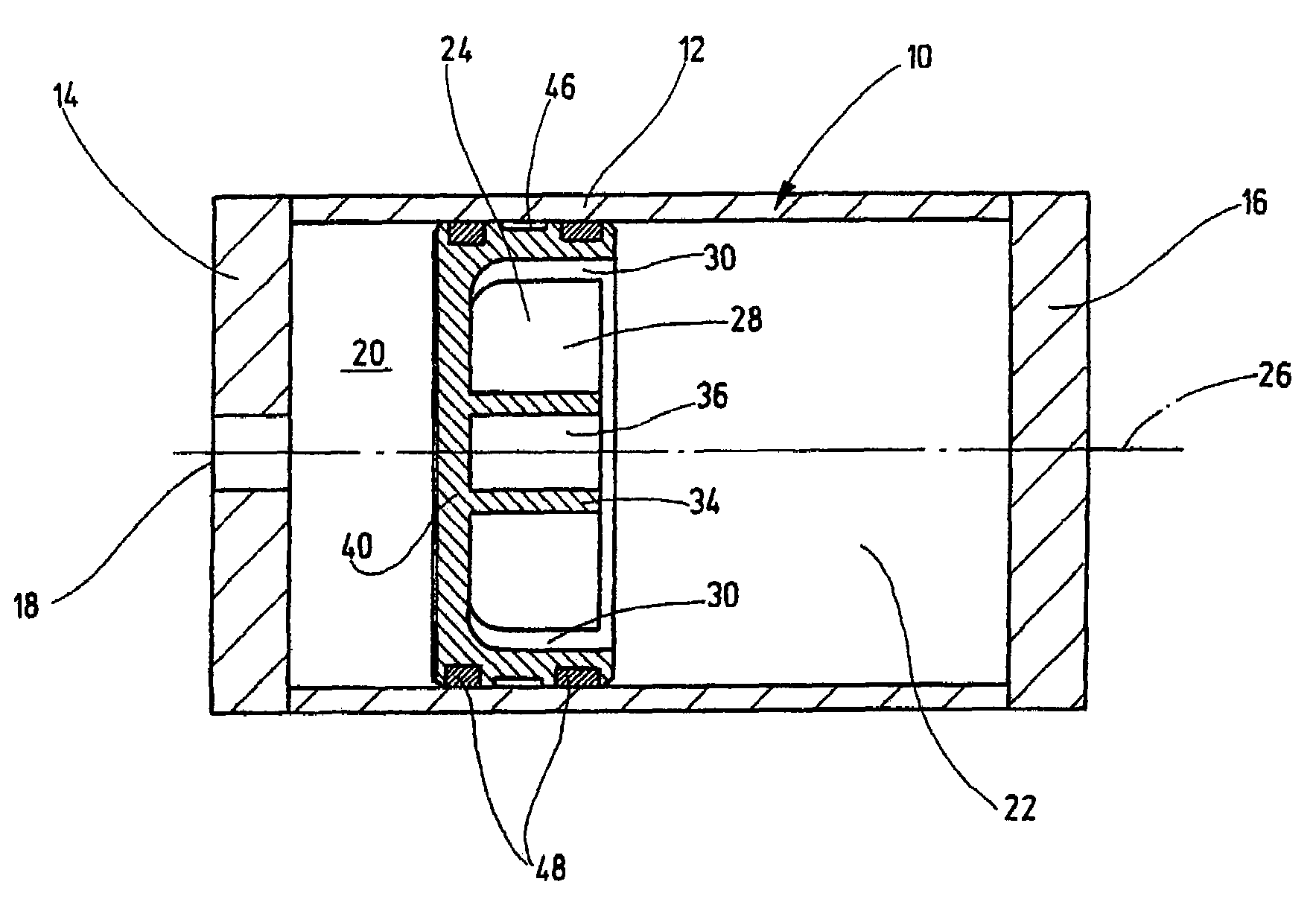
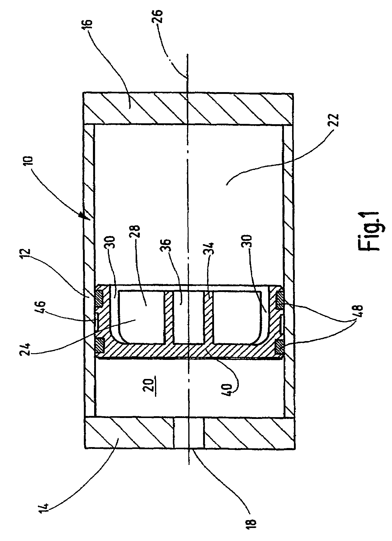
[0016]The piston-type accumulator shown in FIG. 1 has an accumulator housing 10 with a cylindrical jacket or housing 12 (cylinder pipe) sealed on the end sides by two cover parts 14, 16. The cover part 14, the left one as viewed in FIG. 1, has a fluid connection 18 for connecting the separating piston to the piping or conduits of a hydraulic system (not shown), to carry fluid, in order in this way to connect the hydraulic system to the fluid side 20 of the separating piston. The cover part 16, the right one as viewed in FIG. 1, encloses a gas space 22, which can be filled, for example, with nitrogen gas, within the cylindrical jacket 12.

[0017]To refill the gas space 22, also called the gas side of the separating piston, a replenishing valve (not shown) located in the cover part 16 can be used. To separate the fluid side 20 from the gas side 22 within the accumulator housing 10 with its cylindrical jacket 12, a separating piston 24 is axially displaceable back and forth depending on ...


PUM


Abstract

A piston-type accumulator includes a separating piston (24) axially displaced inside an accumulator housing (10) and separating two spaces from one another inside the accumulator housing (10), particularly a gas side (22) from a liquid side (20) of the accumulator. Due to the fact that the separating piston (24) is predominantly or completely made of a plastic material, it can be provided with a very light weight reducing the overall installation weight of the piston-type accumulator.

Description

FIELD OF THE INVENTION[0001]The present invention relates to a piston-type accumulator comprising a separating piston which is axially displaceable within the accumulator housing and which separates two spaces within the accumulator housing from each other, in particular the gas side from the fluid side of the accumulator.BACKGROUND OF THE INVENTION[0002]Piston-type accumulators with gas and fluid sides separated by an axially displaceable piston are known in a plurality of designs. The axially guiding part of the accumulator housing which surrounds the separating piston generally has the shape of a cylinder pipe. For this reason, piston-type accumulators are often called cylinder accumulators. The seal areas on the piston circumference are conventionally formed by ring seals or O-ring seals which are recessed into outer circumferential grooves offset axially to each other in the separating piston.[0003]For use of these cylinder or piston-type accumulators high demands are imposed w...

Claims


Application Information

Patent Timeline
Patent Type & Authority Patents(United States)
IPC IPC(8): F16L55/04F15B1/24F16L55/053
CPCF15B1/24F16L55/053F15B2201/205F15B2201/312F15B2201/3158F15B2201/41F15B2201/4155
Inventor WEBER, NORBERT
Owner HYDAC TECH GMBH
Why Eureka
Try Eureka