Dental device having a sensor film holder with tooth clamp

a technology of sensor film and tooth clamp, which is applied in the field of dental devices, can solve the problems of contamination entering the patient's mouth or tooth, not always easy or comfortable for the patient, and the need to retake the radiograph, so as to reduce the patient's exposure to excessive radiation, improve the accuracy of alignment, and reduce the difficulty of angulation

Inactive Publication Date: 2009-04-14
CEISEL ROBERT J +1
View PDF7 Cites 27 Cited by
  • Summary
  • Abstract
  • Description
  • Claims
  • Application Information

AI Technical Summary

Benefits of technology

[0020]Accordingly, it is a general object of the present invention to provide an improved dental device formed of a sensor film holder with a tooth clamp which eliminates contact of the sensor film holder with patient's fluid or skin and overcomes the disadvantages of the prior art.
[0022]It is another object of the present invention to provide an improved dental device which allows for more precise alignment and reduction in angulation difficulties when taking radiographs during dental procedures, thus reducing patient exposure to excessive radiation due to the retaking of radiographs because of distorted or unfocused images from initially missed alignment. The final result of the RCT will be enhanced due to the increased accuracy of the radiograph, thus improving predictability of treatment for the patient.
[0023]It is another object of the present invention to provide an improved dental device which is cost effective to manufacture and which is relatively easy and non-problematic to use in operation.
[0024]In a preferred embodiment of the present invention, there is provided a dental device which allows for the simple and expedient placement of radiographic sensor film within the oral cavity of a patient without having to remove or adjust the already placed rubber dam. The dental device includes a housing unit for removably holding sensor film, which is attachable to first and second resilient arcuate bridges. Each of the first and second bridges has a first and second end. The first end of the first bridge and the first end of the second bridge are interconnected to corresponding opposite sides of one jaw of a pair of oppositely disposed jaws. The second end of the first bridge and the second end of the second bridge are interconnected to corresponding opposite sides of the other jaw of the pair of oppositely disposed jaws. Each of the oppositely disposed jaws includes a gripping plate, an aperture and a tab for engaging a flexible sheet.

Problems solved by technology

This requires the dentist to either remove the rubber dam completely or at least, with the use of certain sensor film holders, remove the frame of the rubber dam, which is not always easy or comfortable for the patient.
As can be guessed, the possibility of contaminants entering the patient's mouth or tooth is an issue because of the movement of the rubber dam causing leakage and contamination of the field.
More often than not, a patient will inadvertently move during the taking of the radiograph causing the need to retake the radiograph and exposing the patient to additional radiation.
While current technology employs chemicals to sterilize items that are used multiple times, there is still a possibility that the sensor film holder may contain viruses, bacteria, hepatitis B, pirons and / or some other pathogens which are not killed or inactivated.
In efforts to mitigate these germs from contact with the patient, the sensor film holders can be wiped down or have a plastic sheath placed over them, but over time this system can easily be breached.
Although these improvements may have performed so as to lessen the chance of contaminants from coming into contact with patient's skin or fluid and to keep the sensor film steady, these improvements did not eliminate the practice of adjusting the rubber dam in order to place the sensor film between the oral cavity and the underside of the rubber dam.

Method used


Image

  • Dental device having a sensor film holder with tooth clamp
  • Dental device having a sensor film holder with tooth clamp
  • Dental device having a sensor film holder with tooth clamp

Examples


Embodiment Construction

[0033]It is to be distinctly understood at the outset that the present invention shown in the drawings and described in detail in conjunction with the preferred embodiments is not intended to serve as a limitation upon the scope or teachings thereof, but is to be considered merely as an exemplification of the principles of the present invention.

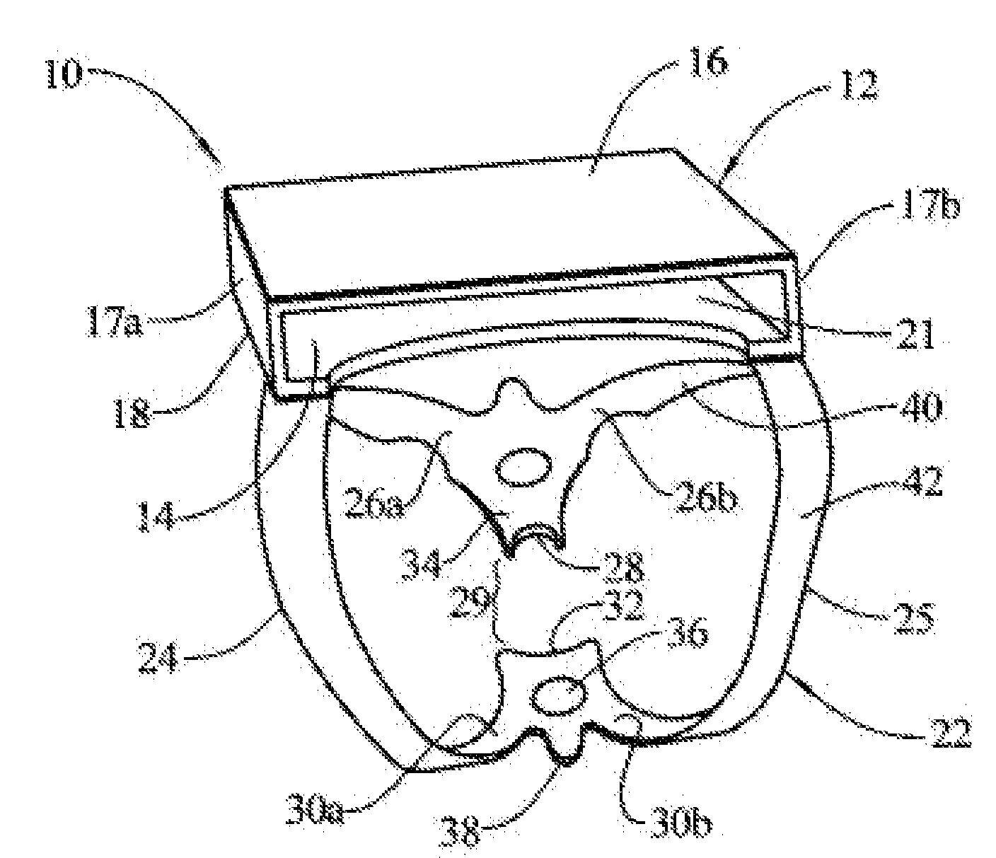
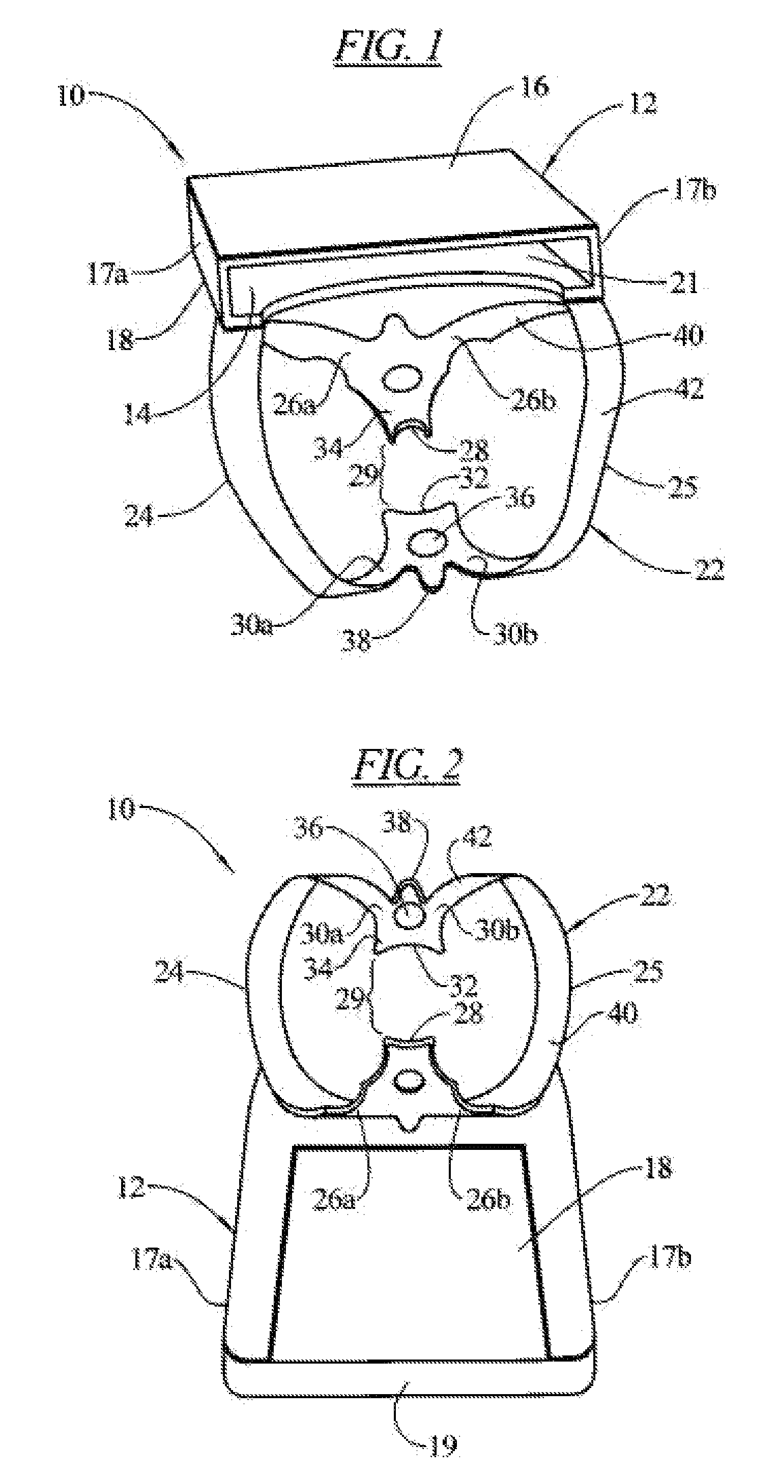
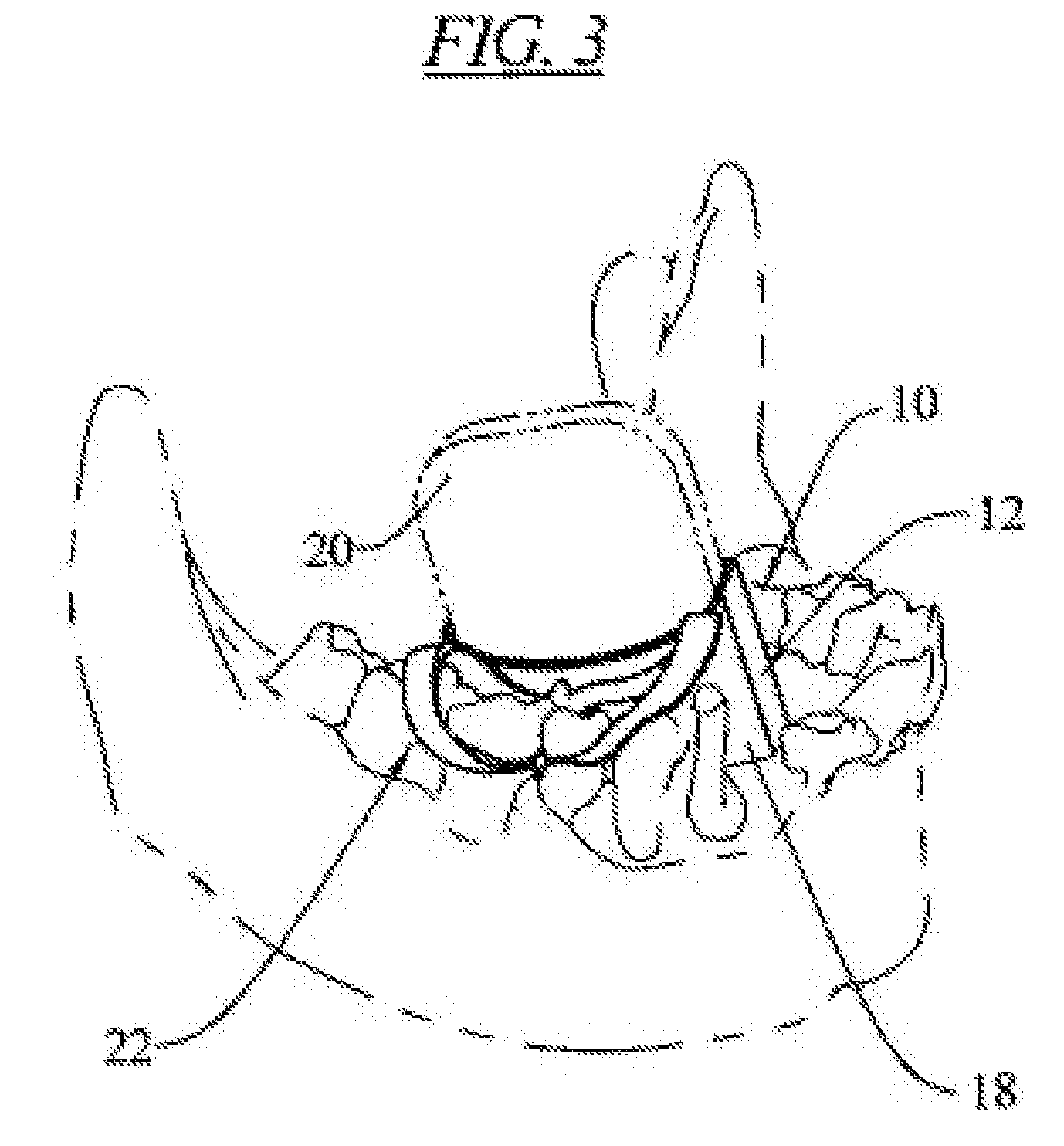
[0034]Referring now in detail to the drawings, wherein like reference characters designate like or corresponding parts throughout the several views, there is illustrated in FIGS. 1 through 4 an improved dental device 10 constructed in accordance with the principles of the present invention. In particular, FIG. 1 is a perspective view of the dental device 10. FIG. 2 is a bottom plan view of the dental device 10. FIG. 3 is a perspective view of the dental device 10 mounted onto a tooth with the rubber dam removed for the sake of clarity in illustration. FIG. 4 is a perspective view of the dental device 10 being mounted onto a tooth with the use...


PUM


Abstract

A dental device includes a housing unit for removably holding sensor film and a tooth clamp disposed on the housing unit. The tooth clamp consists of first and second resilient arcuate bridges. Each of the first and second bridge has a first and second end. The first end of the first bridge and the first end of the second bridge are interconnected to one jaw of a pair of oppositely disposed jaws. The second end of the first bridge and the second end of the second bridge are interconnected to the other jaw of the pair of oppositely disposed jaws. Each of the oppositely disposed jaws includes a gripping plate, an aperture and a tab for engaging a flexible sheet.

Description

BACKGROUND OF THE INVENTION[0001]1. Field of the Invention[0002]This invention relates generally to dental devices, and more particularly, the present invention relates to an improved dental device formed of a sensor film holder with a tooth clamp, which allows, during treatment of a tooth, the simple and expedient placement of radiographic sensor film or digital sensor, within the oral cavity of a patient without having to remove or adjust the already placed rubber dam.[0003]2. Description of the Prior Art[0004]Over the past years, advancements in dentistry have improved greatly, especially since the discovery and use of dental radiography. The applications of dental radiography have enhanced the efficiency and effectiveness of many dental operations, such as in root canal treatment (RCT).[0005]Generally, RCT's and other dental procedures are performed with a flexible sheet, such as a rubber dam, in a surrounding relation to the tooth or teeth undergoing treatment. The rubber dam i...

Claims


Application Information

Patent Timeline
Patent Type & Authority Patents(United States)
IPC IPC(8): A61B6/14A61C5/12
CPCA61C5/12A61C5/122G03B42/042A61C5/80A61C5/82
Inventor CEISEL, ROBERT J.CEISEL, EMILY M.
Owner CEISEL ROBERT J
Why Eureka
Try Eureka