Metal band as inlay for trim strips or sealing strips

a technology of metal bands and sealing strips, applied in the field of metal bands, can solve the problems of high cost of metal bands coated with adhesive means, high cost of cutting to length of sealing strips on site, and the need to cut to length of clamping sections which continuously exit the extruder relatively fast, etc., and achieves the effect of facilitating cutting to length and low energy inpu

Active Publication Date: 2009-04-14
BFC FAHRZEUGTEILE GMBH
View PDF7 Cites 10 Cited by
  • Summary
  • Abstract
  • Description
  • Claims
  • Application Information

AI Technical Summary

Benefits of technology

[0008]It is the underlying object of the invention to provide a metal band of the initially named kind which does not have these disadvantages. In particular the cutting to length should be facilitated and made possible with a low energy input.

Problems solved by technology

The continuously produced metal bands are jacketed by rubber and / or flexible plastic and have slots in order, among other things, to permit a penetration of the sealing material with metal bands not coated with an adhesive means, since the adhesion of rubber to metal or plastic to metal is not possible.
On the other hand, metal bands coated with an adhesive means are very expensive.
In addition, the clamping section should be compressible in the longitudinal direction, since the openings to be sealed can have substantial peripheral tolerances and a cutting to length of the sealing strip on site would be extremely time-consuming and / or expensive.
The difficulty exists in this process that a clamping section which continuously exits the extruder relatively fast has to be cut to length in a discontinuous workstep.
The available time for the cutting through is therefore very short.
A high energy input has the result that the materials which surround the metal band such as rubber, PVC and other sealants are impaired and the metal band is exposed too much.
In addition to the visual degradation of the product, the risk of injury is thereby increased, on the one hand, and the vulcanizing together of the two ends of the sealing strip is made more difficult, on the other hand.
There is the risk that the metal band will corrode with sealing strips which are not vulcanized or are vulcanized badly.

Method used


Image

  • Metal band as inlay for trim strips or sealing strips
  • Metal band as inlay for trim strips or sealing strips
  • Metal band as inlay for trim strips or sealing strips

Examples


Embodiment Construction

[0030]The following description of the preferred embodiment(s) is merely exemplary in nature and is in no way intended to limit the invention, its application, or uses.

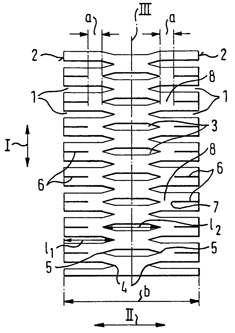
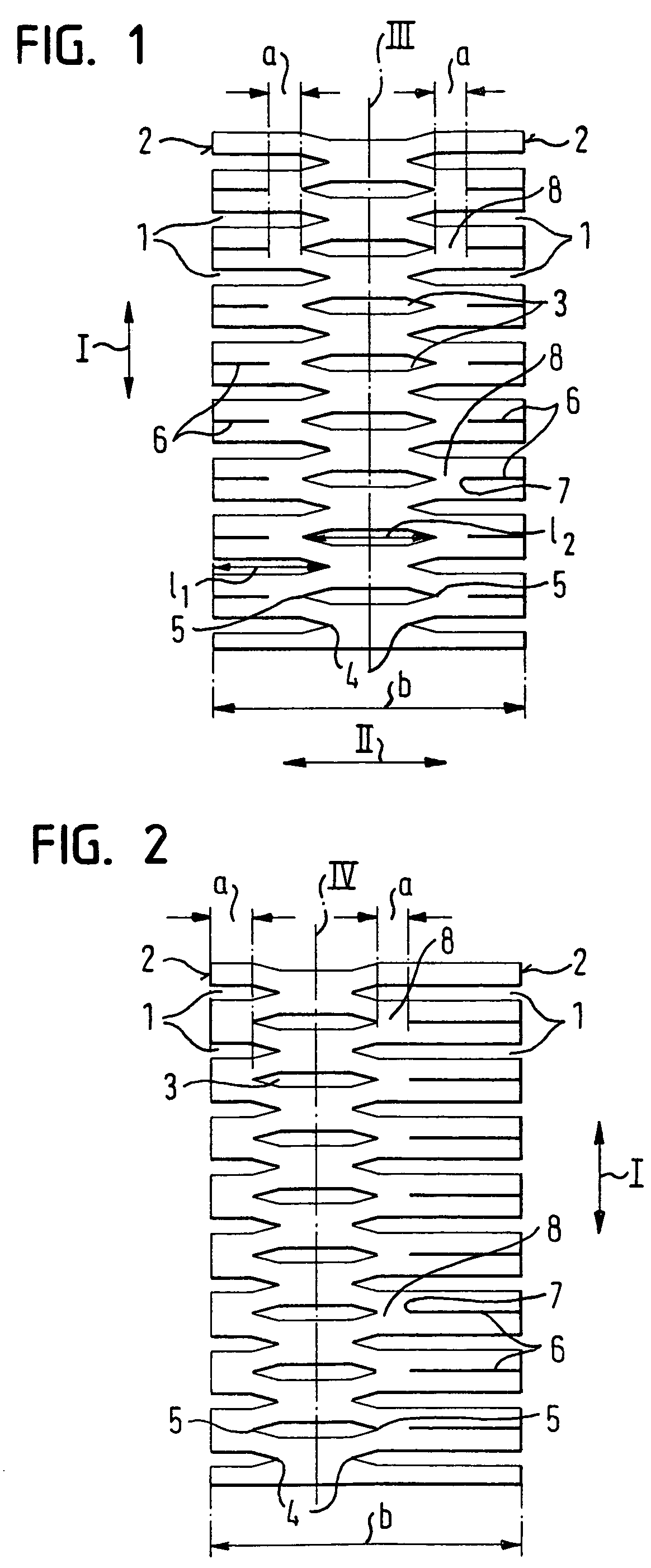
[0031]The metal band which is shown in FIG. 1 and which can be used as an inlay for trim strips or sealing strips of a flexible material, in particular of rubber or plastic, has a plurality of edge slots 1 which are periodically sequential in the longitudinal direction I of the band and are inwardly guided from the two edges 2 of the metal band lying oppositely disposed to one another in pairs. The edge slots 1 have a length l1 which corresponds to approximately three eighths of the width b of the metal band. The metal band furthermore has a respective central slot 3 between two respective sequential pairs of edge slots 1, the length l2 of said central slot amounting to approximately half the band width b. The central slots 3 thereby overlap the edge slots 1 slightly in the transverse direction II of the metal band, n...


PUM

PropertyMeasurementUnit
lengthaaaaaaaaaa
lengthaaaaaaaaaa
sizeaaaaaaaaaa

Abstract

A metal band inlay for trim strips or sealing strips of flexible material that is bent to form a section. The metal band includes a plurality of edge slots in the longitudinal direction, which are guided inwardly from an edge of the metal band transversely to the longitudinal direction. The edge slots are wedge shaped. Central slots run to a tip toward their respective two ends and are arranged between the sequential edge slots. The central slots extend transversely to the longitudinal direction, but do not extend up to the edge. To simplify the cutting, the metal band further includes throughcuts that extend transversely to the longitudinal direction of the metal band, that correspond to at least some of the central slots and that extend from at least one edge of the metal band in the direction toward the tip of the respective central slot disposed opposite to the edge.

Description

CROSS-REFERENCE TO RELATED APPLICATIONS[0001]This application claims the benefit of German Utility Model No. DE 20 2005 002 832.0, filed on Feb. 22, 2005, the disclosure of which is incorporated herein by reference.FIELD OF THE INVENTION[0002]The present invention relates to a metal band as an inlay for trim strips or sealing strips of flexible material, in particular of rubber or plastic, which is in particular bent to form a section, having a plurality of slots, in particular periodically sequential slots in the longitudinal direction of the band which are inwardly guided from one edge of the metal band transversely to its longitudinal direction, which are wedge shaped or which run out inwardly in wedge shape, and central slots which run out to a tip at their two ends, are arranged between sequential edge slots in the longitudinal direction, likewise extend transversely to the longitudinal direction of the metal band, but are not guided up to the edge.BACKGROUND OF THE INVENTION[0...

Claims


Application Information

Patent Timeline
Patent Type & Authority Patents(United States)
IPC IPC(8): B32B3/24B21B5/00B21D25/00B21D28/26B32B3/02B60R13/04B60R13/06F16B5/12
CPCB60J10/0011Y10T24/30Y10T428/12368Y10T428/12396Y10T428/12201Y10T428/12361B60J10/18
Inventor WAGNER, JOACHIM
Owner BFC FAHRZEUGTEILE GMBH
Why Eureka
Try Eureka