Supercharge Your Innovation With Domain-Expert AI Agents!

Circuit module

a technology of circuit modules and circuits, applied in the field of circuit modules, can solve the problems of achieve the effect of enhancing the density of board packaging and reducing the diameter of through holes

Active Publication Date: 2009-04-14
AUTONETWORKS TECH LTD +2
View PDF16 Cites 12 Cited by
  • Summary
  • Abstract
  • Description
  • Claims
  • Application Information

AI Technical Summary

Benefits of technology

This design facilitates accurate visual inspection of soldered regions, ensuring reliable electrical connections and reducing the thickness of the circuit module while maintaining high packaging density.

Problems solved by technology

This disadvantage becomes prominent as a diameter of the through-hole is reduced to enhance board packaging density.

Method used


Image

  • Circuit module
  • Circuit module
  • Circuit module

Examples


Embodiment Construction

[0020]A preferred embodiment of the present invention will be described based on the drawings. The basic constitution of a circuit module and a production process therefor according to this embodiment are equivalent to those disclosed in the aforementioned Patent Publication 1. Thus, the basic configuration will be described only about an outline thereof.

[0021]Firstly, there is described one example of a production process for a circuit module. However, a circuit module according to the present invention is not limited to a product produced by the following process.

[0022](1) Bus Bar Forming Process

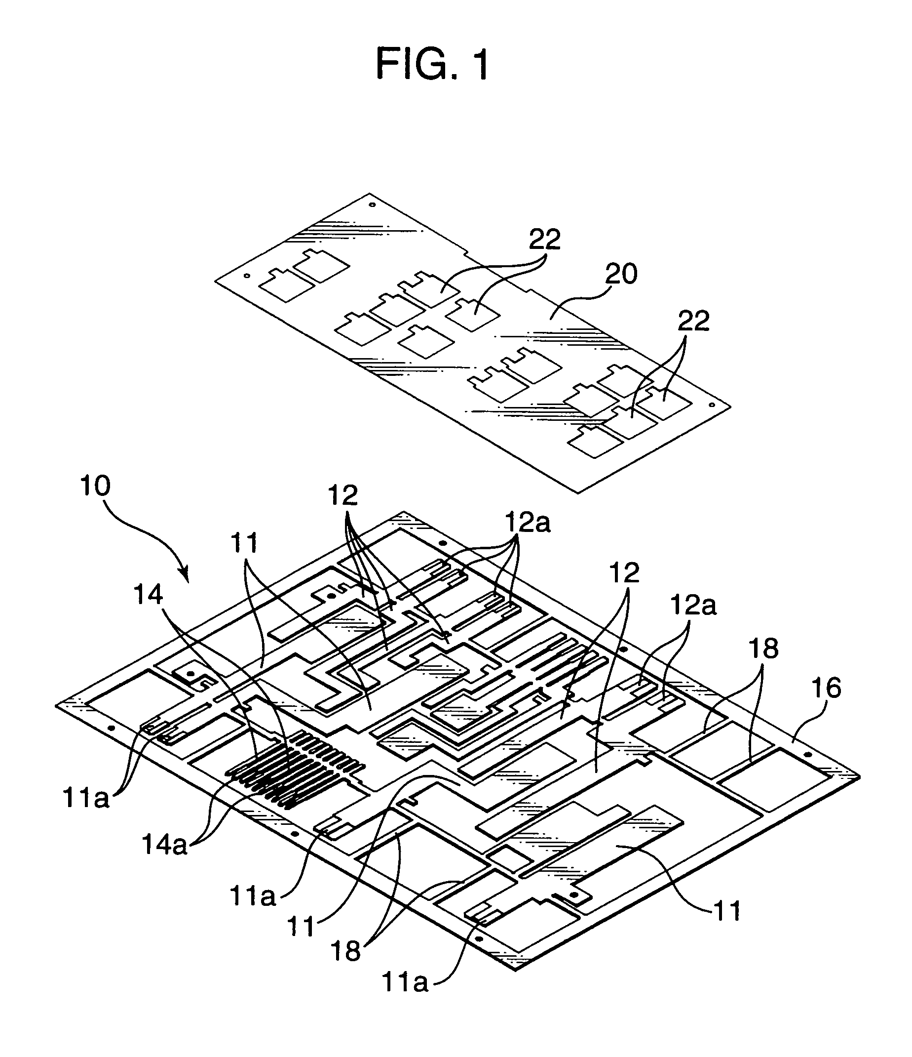
[0023]For producing the circuit module, there is formed a bus bar plate element 10 as shown in FIG. 1.

[0024]The illustrated bus bar plate element 10 comprises a rectangular-shaped outer frame 16, inside which a large number of bus bars including a plurality of input-terminal bus bars 11 each adapted to form an input terminal, a plurality of output-terminal bus bars 12 each adapted to form ...


PUM


Abstract

In respect to an electrical connection between a control circuit board 20 and bus bars 14 interbonded together, it is an object to enhance stability in quality and reliability in connection. As a solution for achieving the object, the control circuit board 20 is provided with a conductor segment 26 to be electrically connected to a specific one of the bus bars 14 on the opposite side of a rear surface thereof bonded to the bus bars 14, and a through-hole 24 penetrating a main body thereof at a position adjacent to the conductor segment 26 so as to expose the specific bus bar 14 therethrough. Further, an electrically-connecting member 70 is disposed to bridge over the through-hole 24 and the conductor segment 26, and soldered onto the conductor segment 26 and the bus bar portion located in the through-hole 24.

Description

TECHNICAL FIELD[0001]The present invention relates to a circuit module having a combination of a plurality of bus bars to form a power circuit to be mounted on an automobile or the like, and a control circuit board in which a control circuit for the power circuit is built.BACKGROUND ART[0002]Heretofore, as means for distributing electric power from a common vehicle-mounted power supply to respective electronic units, there has been widely known an electric junction box comprising a power distribution circuit formed by laminating a plurality of bus bar boards, and a circuit control element, such as a fuse and a relay switch, inserted in the power distribution circuit.[0003]Late years, with a view to downsizing the distribution circuit unit, a circuit module as disclosed in the following Patent Publication 1 has been developed. This circuit module is designed such that a plurality of bus bars forming a power circuit are arranged approximately in the same plane and bonded on one of opp...

Claims


Application Information

Patent Timeline
Patent Type & Authority Patents(United States)
IPC IPC(8): H01R9/00H01R11/01H02G3/16H05K1/02H05K1/14H05K3/20H05K3/34H05K3/40H05K7/06
CPCH05K1/0263H05K3/202H05K3/4046H05K1/141H05K3/341H05K3/3447H05K2201/0394H05K2201/10272H05K2201/1028H05K2201/10295H05K2201/10363
Inventor SHIMIZU, TOSHIKITAKAGI, KOUICHIMIZUNO, FUMIAKI
Owner AUTONETWORKS TECH LTD
Features
  • R&D
  • Intellectual Property
  • Life Sciences
  • Materials
  • Tech Scout
  • Unparalleled Data Quality
  • Higher Quality Content
  • 60% Fewer Hallucinations
Learn More