
Input/output (I/O) scanner for a control system with peer determination

Inactive Publication Date: 2009-04-14
SCHNEIDER AUTOMATION INC
View PDF101 Cites 9 Cited by
  • Summary
  • Abstract
  • Description
  • Claims
  • Application Information

AI Technical Summary

Benefits of technology

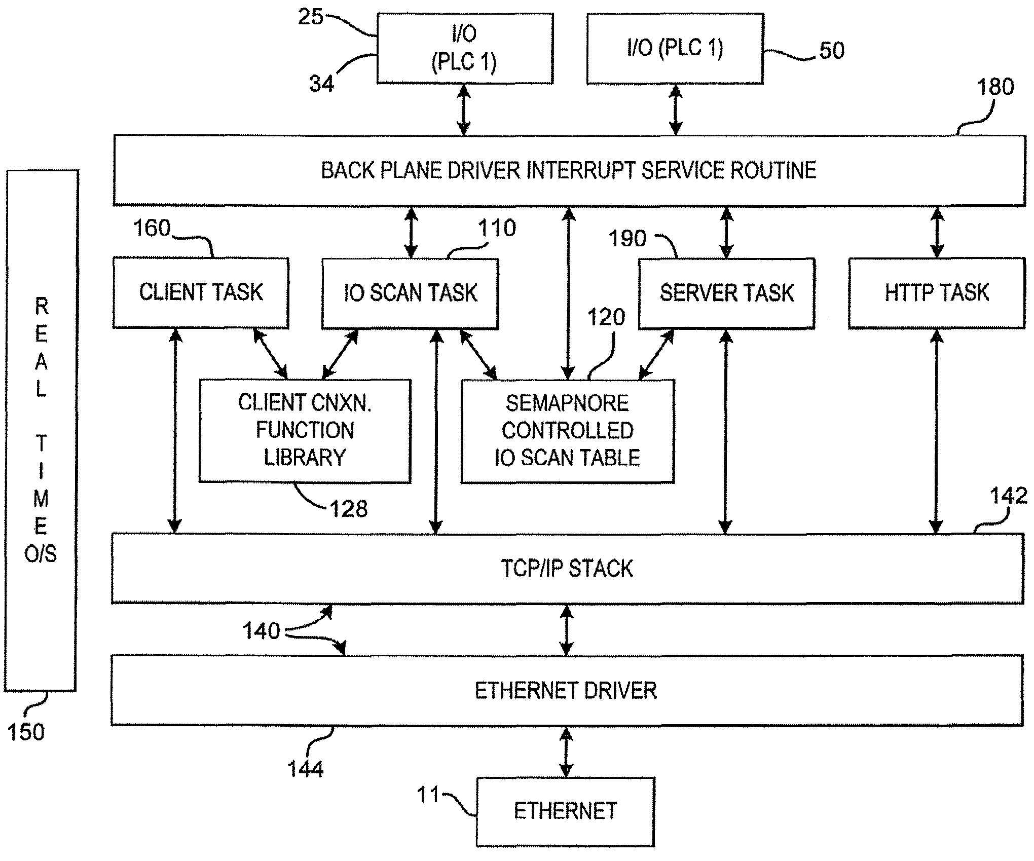
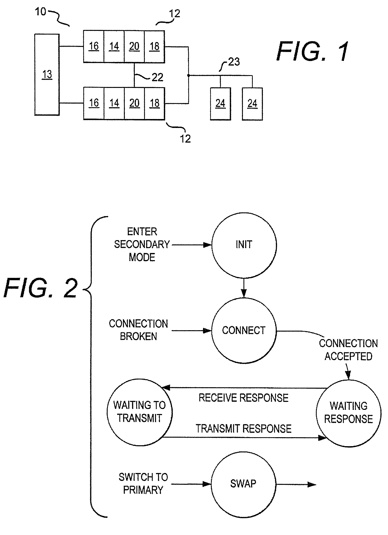
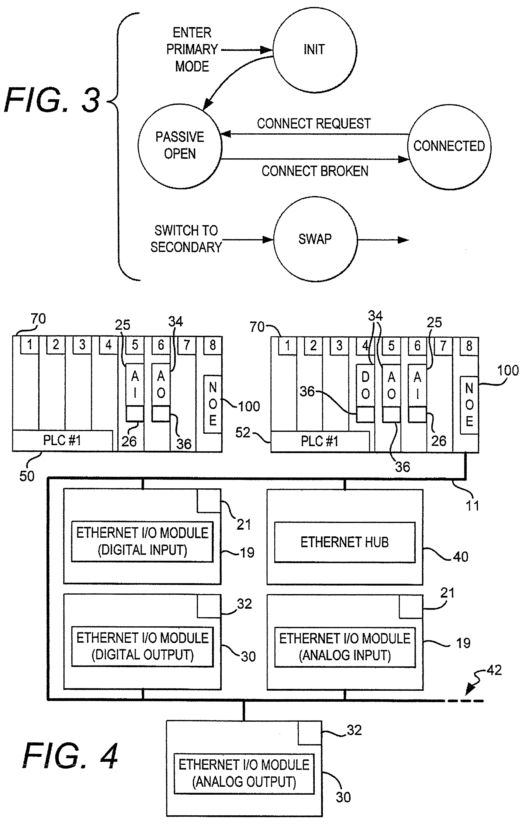
[0009]The present invention is a method and an apparatus for exchanging programmable logic controllers (PLC) of a control system configured in an active standby, duplex or redundant set-up on an Internet Protocol (IP) network. Accordingly, the associated network address identifier of the PLCs are also exchanged. The control system operates normally until a failure in the primary mode PLC is detected. Upon detecting a primary mode PLC failure, the secondary mode PLC configured in active standby is substituted in place of the failed primary mode PLC, along with the associated IP address. The exchanging of the PLCs is accomplished without significantly disrupting the performance of the overall control system by substantially suspending or delaying the network's operation. Alternatively, the Media Access Control (MAC) address of controllers can also be exchanged.
[0010]It is an object of this invention to provide an active standby control system integrated on a network capable of replacing a PLC unit without significantly disrupting the performance of the control system or the communication network.

Problems solved by technology

Using proprietary control networking protocols, resulted in high installation costs, low ease-of-use, and compatibility problems with other devices / systems used in control systems, such as in factory automation applications.
Network problems arise when a device or PLC fails and must be replaced.
The failing network PLC cannot be readily exchanged with a PLC configured in active standby because the network address identifier assigned to the PLC to be removed is not readily associated with the active standby PLC.

Method used


Image

  • Input/output (I/O) scanner for a control system with peer determination
  • Input/output (I/O) scanner for a control system with peer determination
  • Input/output (I/O) scanner for a control system with peer determination

Examples


Embodiment Construction

[0024]While this invention is susceptible of embodiments in many different forms, there is shown in the drawings and will herein be described in detail preferred embodiments of the invention with the understanding that the present disclosure is to be considered as an exemplification of the principles of the invention and is not intended to limit the broad aspect of the invention to the embodiments illustrated.

[0025]The subject matter of the present application is related to the following commonly assigned applications: U.S. patent application Ser. No. 08 / 927,005 filed on Sep. 10, 1997, entitled “Web Interface To A Programmable Controller;” U.S. patent application Ser. No. 09 / 224,196 filed Dec. 30, 1998, entitled “Input / Output (I / O) Scanner For A Control System With Peer Determination;” U.S. patent application Ser. No. 09 / 303,458 filed Apr. 30, 1999, entitled “Web Interface To A Programmable Controller;” U.S. Pat. No. 6,061,603 issued May 9, 2000, entitled “A System For Remotely Acce...


PUM


Abstract

A method and apparatus for providing an active standby control system includes the steps of providing a first and second programmable logic controller (PLC), each controller having an operating state. Each controller includes a network module board operably connected to a network; a control unit, a remote I / O head; and, a hot standby module, each hot standby module is operably connected together. PLC. This method and apparatus can be used within a control system for monitoring input devices and for controlling output devices which reside on the standard communications network such as an Ethernet network, and the standard communications protocol used therein can be TCP using Modbus.

Description

RELATED APPLICATIONS[0001]This patent application claims priority to U.S. patent application Ser. No. 09 / 612,636, filed Jul. 7, 2000, entitled, “A Method And Apparatus For An Active Standby Control System On A Networks,” now U.S. Pat. No. 7,032,029, issued Apr. 18, 2006; which application claims priority to U.S. patent application Ser. No. 09 / 224,196, filed Dec. 30, 1998, entitled, “Input / Output (I / O) Scanner For A Control System With Peer Determination,” now U.S. Pat. No. 6,327,511, issued Dec. 4, 2001; the contents of these applications are expressly incorporated herein by reference.TECHNICAL FIELD[0002]The present invention relates to a control system incorporating programmable logic controllers (PLC). More particularly, the present invention relates to backup PLCs on a network.[0003]Additionally, the present invention relates to an apparatus and method for determining the type of a communication device using known communication protocols over standard networks, and for moving da...

Claims


Application Information

Patent Timeline
IPC IPC(8): G06F15/16G05B9/03G05B19/05
CPCG05B9/03G05B19/058G05B2219/14132
Inventor NAISMITH, RONTANZMAN, ALLANPAPADOPOULOS, DEANSWALES, ANDYMETCALF, ORLANDO P.
Owner SCHNEIDER AUTOMATION INC
Features
  • Generate Ideas
  • Intellectual Property
  • Life Sciences
  • Materials
  • Tech Scout
  • Unparalleled Data Quality
  • Higher Quality Content
  • 60% Fewer Hallucinations
Learn More