Thin film magnetic head and fabrication process for preventing short-circuit failure in a narrow track width and narrow gap length

a thin film, magnetic head technology, applied in shielding heads, instruments, data recording, etc., can solve the problems of increasing the possibility of short-circuit generation, decreasing isolation voltage, and becoming fatal, so as to prevent short-circuit failure, reduce capacitance, and improve yield

Inactive Publication Date: 2009-04-21
WESTERN DIGITAL TECH INC
View PDF10 Cites 3 Cited by
  • Summary
  • Abstract
  • Description
  • Claims
  • Application Information

AI Technical Summary

Benefits of technology

[0009]In FIG. 2(a), the upper shield 11 and lower shield 1, which also work as the leads, are connected to each other through the CPP film 3 being a sensor film. The flow of signal current passes to the lower shield 1 from, for instance, the upper shield through the CPP film 3. If the current flows without passing through the CPP film 3, a decrease in output is caused by a shunt loss. Therefore, as shown in FIG. 2(a), the insulation performance between the upper shield 11 and the lower shield 1 is ensured by using the insulating film 2, insulating film 5, insulating film 8, and insulating film 10. Moreover, the insulating film 5 connected to the CPP film 3 keeps the insulation performance of the wall surface of the CPP film 3. The domain control film 6 (or sub-shield film) connected on the insulating film 5 has almost the same shape as the insulating film 5.
[0015]Additionally, the aforementioned JP-A No. 280635 / 2002 is about an improvement in the insulation barrier layer, and it does not describe the insulating characteristics around the sensor film. In JP-A No. 198000 / 2003 and JP-A No. 298144 / 2003, it is thought to be possible to make the insulating films thicker from the upper and lower lead structures to the inside of the sensor film, thereby improving the insulation voltage. However, there is concern that neighboring signals recorded on the magnetic recording media are read at the sensor film except for the part connected to the leads. Because of this, there is a possibility that an abnormal signal is generated, and improvement of the recording density becomes difficult.
[0016]Concerning the problems of the above-mentioned prior art, it is a feature of the present invention to provide a thin film magnetic head and the fabrication process thereof, in which yield can be improved by maintaining the insulation voltage between the upper and lower leads and preventing short-circuit failure in a narrow track width and a narrow gap length. Embodiments of the present invention provide a new pattern shape.
[0024]According to the features described above, keeping the insulation voltage between the upper and lower leads and preventing the short-circuit failure become possible even in a narrow track width and narrow gap length, resulting in improved yield. Moreover, it also becomes possible to decrease the capacitance and improve the frequency characteristics by reducing the narrow gap area between the upper and lower leads. Furthermore, the recording density is increased by mounting a thin film magnetic head of the present invention, thereby, disk device with excellent frequency characteristics can be obtained with high yield.
[0025]According to the present invention, yield can be improved by keeping the insulation voltage between the upper and lower leads and preventing short-circuit failure even in a narrow track width and narrow gap length.

Problems solved by technology

In the case when an electric current flows perpendicular, if an unnecessary current path, that is, short-circuit develops between the upper and lower leads, this would become a fatal defect.
Moreover, in the case when the isolation voltage between the upper and lower leads decreases, the event probability of short-circuit failure increases, resulting in a decrease in yield.
Because of this, it is thought that the possibility of short-circuit generation and of decreased isolation voltage increases more and more.
There is concern that the high frequency characteristics become worse when the capacitance increases.
Therefore, improving the recording density is thought to be difficult due to worsening of the high frequency characteristics.

Method used


Image

  • Thin film magnetic head and fabrication process for preventing short-circuit failure in a narrow track width and narrow gap length
  • Thin film magnetic head and fabrication process for preventing short-circuit failure in a narrow track width and narrow gap length
  • Thin film magnetic head and fabrication process for preventing short-circuit failure in a narrow track width and narrow gap length

Examples


Embodiment Construction

[0040]Hereafter, the embodiment of the present invention will be described referring to the drawing. A thin film magnetic head of the present invention is usually used for a read head and used in combination with a write head. If there is no special description in the following explanations, a write head part is omitted and only a read head part is described. Additionally, in each of the following figures, the same composition part will be shown using the same code.

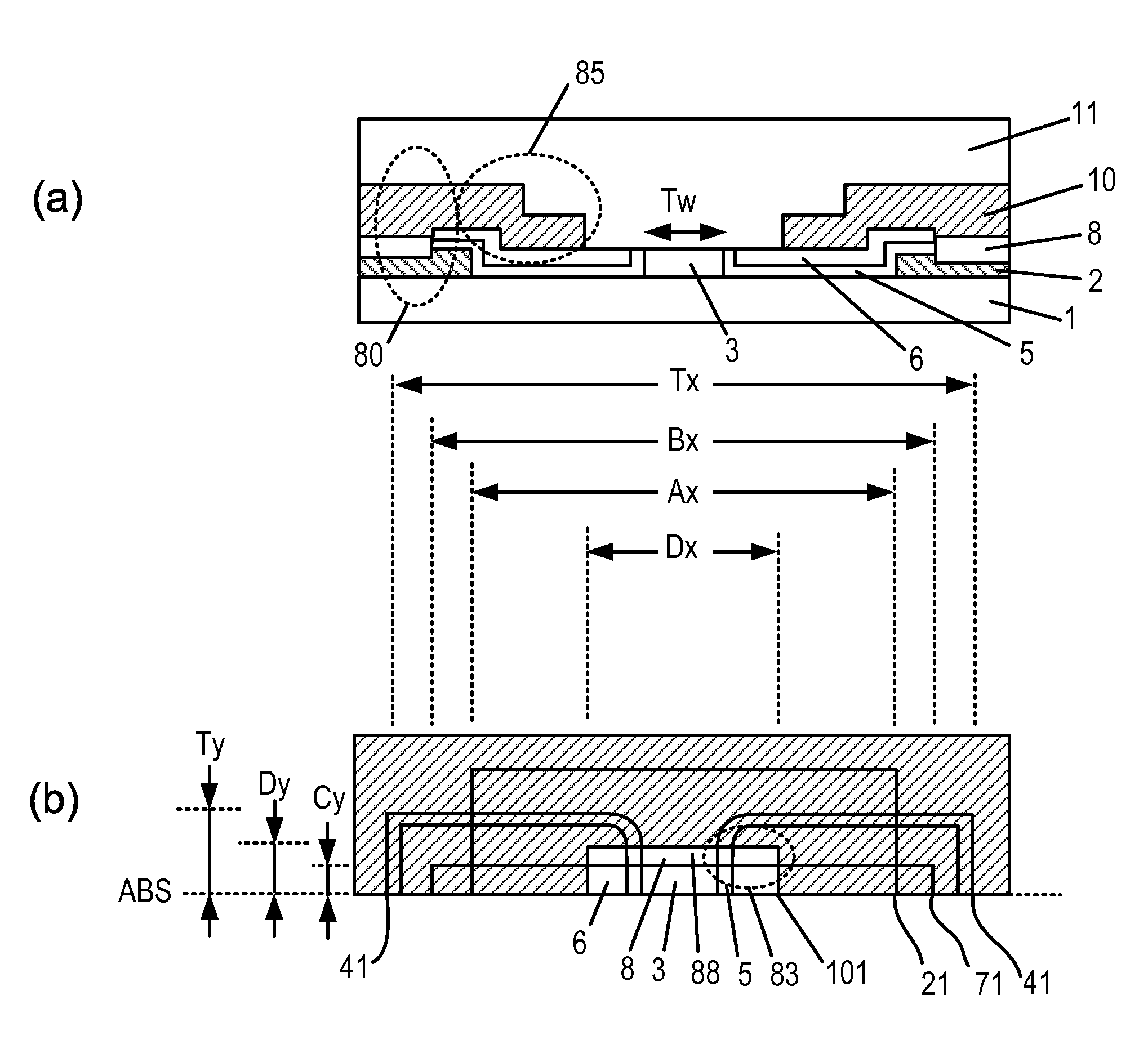
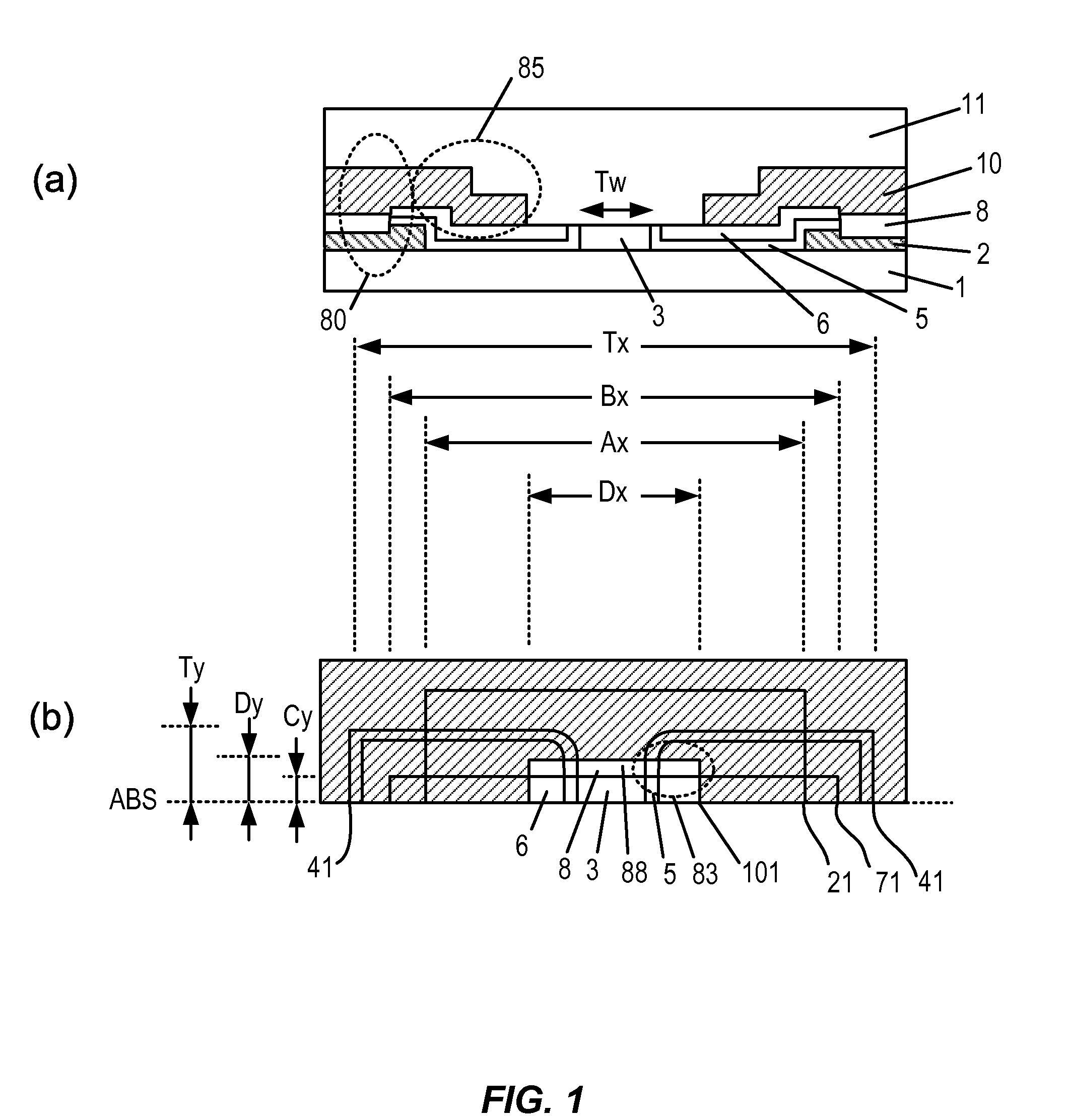
[0041]FIG. 1 is a schematic drawing illustrating an example of a thin film magnetic head of the present invention. FIG. 1(a) is a drawing seen from the air bearing surface, and FIG. 1(b) is a plan projection drawing.

[0042]In FIG. 1(a), the upper shield 11 and lower shield 1, which are the leads, are connected to each other through the CPP film 3 being the sensor film. The signal current flows to the lower shield 1 from, for example, the upper shield 11 through the CPP film 3. Therefore, as shown in FIG. 1(a), the insulati...


PUM

PropertyMeasurementUnit
thicknessaaaaaaaaaa
distanceaaaaaaaaaa
lengthaaaaaaaaaa

Abstract

Embodiments of the invention relate to preventing short-circuit failure even in the narrow track width and narrow gap length, resulting in improved yield. In one embodiment, die sensor heads are placed on both sides of the track direction of the sensor film. The sensor heads comprise the first insulating film with at least a part connected to the track direction wall surface of the sensor film and the third insulating film formed between the upper shield and the first insulating film, and have the relationship being Tw<Dx<Bx where the distance between edges of the first insulating film connected to the track direction wall surface of the sensor film is Tw, the distance between outside edges of the first insulating film along the track direction Bx, and the distance of inside edges of the third insulating film along the track direction Dx.

Description

CROSS-REFERENCES TO RELATED APPLICATIONS[0001]This application claims priority from Japanese Patent Application No. JP2004-209135, filed Jul. 15, 2004, the entire disclosure of which is incorporated herein by reference.BACKGROUND OF THE INVENTION[0002]This invention relates to a thin film magnetic head which is applied to magnetic disc storage. More particularly, it relates to a thin film magnetic head used for reproducing.[0003]With improving the high recording density of an HDD (Hard Disk Drive), a thin film magnetic head mounted in it requires even narrower track width, narrower gap length, and higher sensitivity. At present, a thin film magnetic head is used by combining a write head with a read head. A GMR head applying the GMR effect is mainly used for the read head. This GMR head is a CIP (Current In Plane) type head in which an electric signal flows parallel in the film surface of a sensor film. For further improvement of the recording density in the future, a TMR (Tunneling...

Claims


Application Information

Patent Timeline
Patent Type & Authority Patents(United States)
IPC IPC(8): G11B5/39G11B5/11
CPCG11B5/127G11B5/33
Inventor YOSHIDA, NOBUO
Owner WESTERN DIGITAL TECH INC
Why Eureka
Try Eureka