
Process meter

a technology of process meter and meter, which is applied in the direction of liquid/fluent solid measurement, machines/engines, instruments, etc., can solve the problems of vibration caused vibration with considerable amplitude in the electronics case, and vibration caused in the sensor or generated, etc., and achieve the effect of rubbed construction

Active Publication Date: 2009-04-28
ENDRESS HAUSER FLOWTEC AG
View PDF20 Cites 6 Cited by
  • Summary
  • Abstract
  • Description
  • Claims
  • Application Information

AI Technical Summary

Benefits of technology

[0028]One advantage of the invention is that the measurement signal can be evaluated with a comparatively small amount of circuitry, particularly with conventionally used meter electronics.
[0029]Another advantage of the invention is that the use of such a vibration absorber affixed to a wall of the electronics case necessitates virtually no changes in the area of the process-signal terminals and interfaces, such as in the sensor components that may be housed in the electronics case. In addition, such a vibration absorber in the form of, e.g., a metal body embedded in a plastic body can be very simple and, thus, very rugged in construction.

Problems solved by technology

However, any vibrations caused in the sensor or generated in the process and transmitted via the sensor, such as vibrations or pressure surges in a connected pipe, can be coupled into the electronics case nearly undamped.
This coupling in vibrations, which is practically unavoidable particularly in the case of rigid connections, may, in turn, lead to vibrations with considerable amplitudes in the electronics case.
Acceleration forces or bending moments resulting from the case vibrations represent an increased mechanical load on the field meter as a whole and on the sensor supporting the electronics case in particular.
If the case where vibrations have a resonant frequency which would lie approximately in the measuring range of the sensor or even in the range of a, e.g. operationally variable, frequency of the measurement signal, a separation of the useful component in the measurement signal from any spurious components may become virtually impossible.
At any rate, since the meter electronics processing the measurement signal must be controllable over a comparatively wide signal level range and be highly selective while having a comparatively wide signal bandwidth, this separation of the useful component would require a considerable amount of additional circuitry, which would significantly increase the circuit complexity of the meter electronics and thus add to the manufacturing costs of the field meter.

Method used


Image

  • Process meter
  • Process meter
  • Process meter

Examples


Embodiment Construction

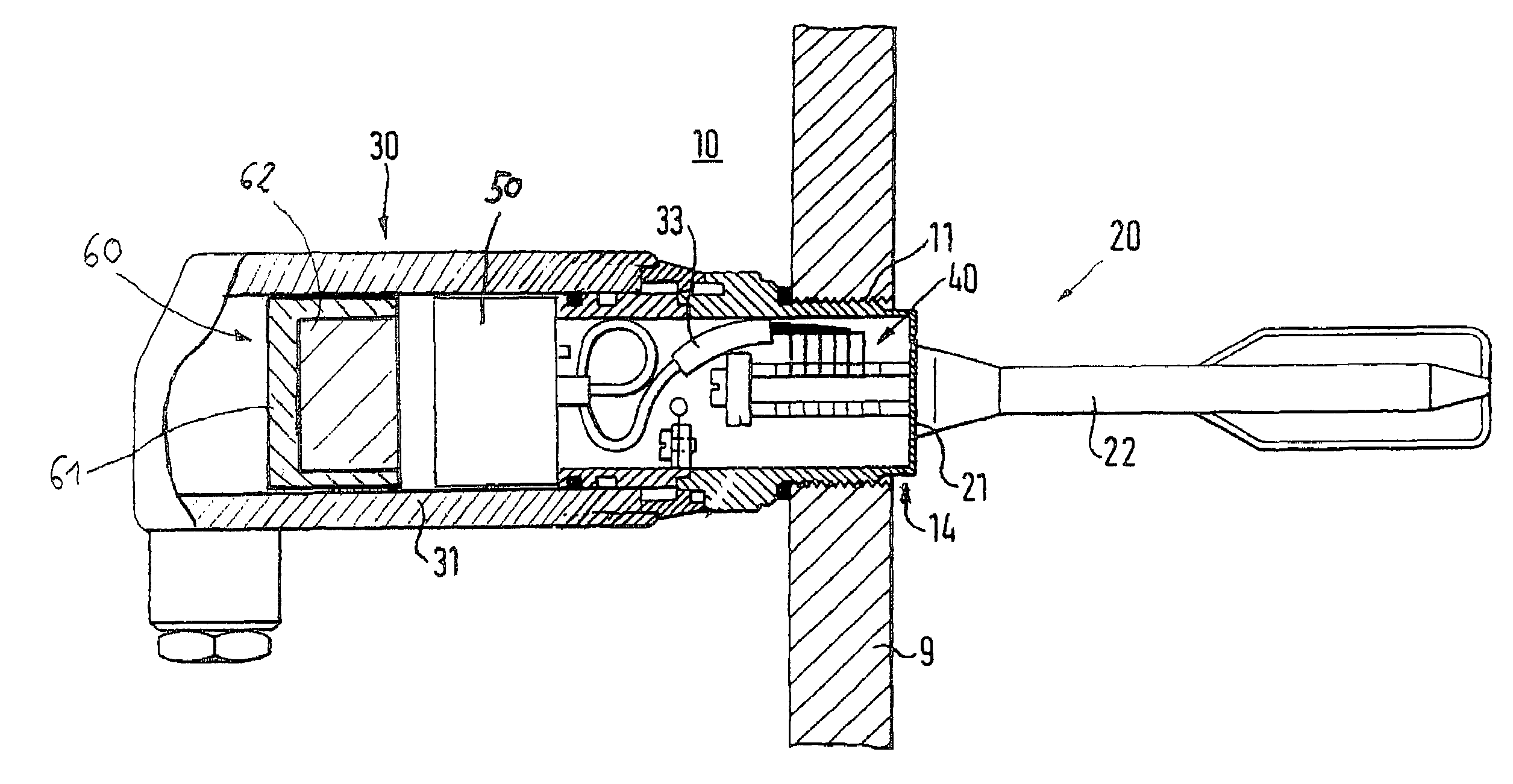
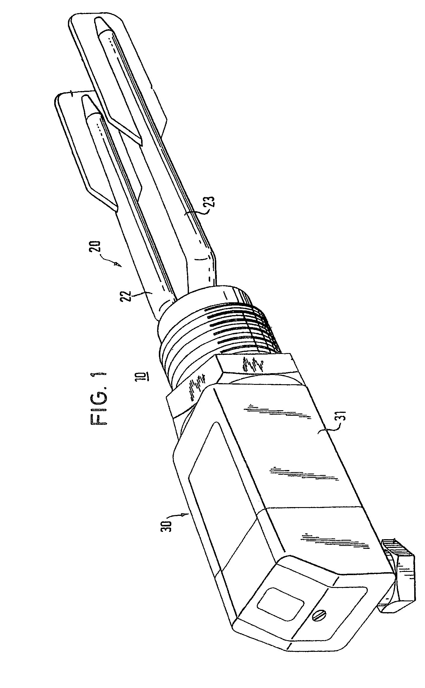
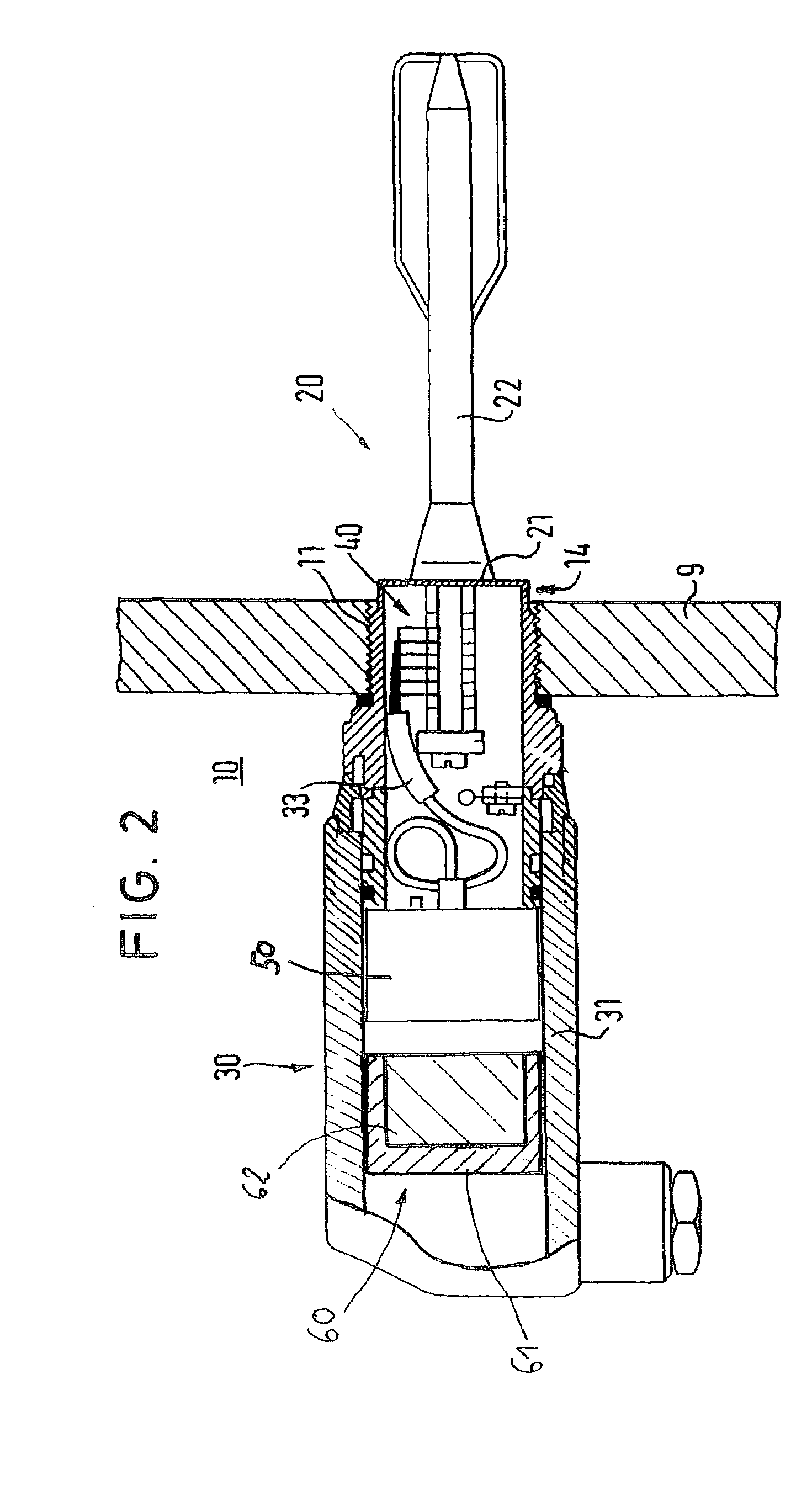
[0035]In FIGS. 1 and 2, an embodiment of a process meter 10 is shown schematically in different views.

[0036]The process meter shown, 10, is a level limit monitor, which serves to determine and / or monitor the presence of the process medium in a vessel or whether the process medium has reached a predetermined level. To that end, process meter 10 is fixed by means of a threaded connection 11 in a wall 9 of a vessel (not shown) holding or conveying a process medium, for instance a liquid or a powder, e.g. in a tank or pipe. The construction and use of such level limit monitors, particularly their mechanical design and circuit design as well as methods of operating them, are described in detail in EP-A 984 248, U.S. Pat. Nos. 4,594,584, 5,844,491, 5,966,983, 6,138,507, and 6,236,322, for example.

[0037]To sense the level and generate a measurement signal representative thereof, process meter 10 comprises a sensor 20 in the form of a physical-to-electrical transducer, which touches the med...


PUM


Abstract

The process meter comprises a sensor that can be mounted in a wall of a vessel for holding or conveying a process medium, and a meter-electronics case mechanically coupled to the sensor. In operation, the electronics case is at least intermittently subjected to vibrations either generated in the sensor itself or transmitted via the sensor. To reduce amplitudes of such vibrations of the electronics case, at least one vibration absorber is affixed to a wall of the electronics case. This vibration absorber is vibrated at least intermittently in order to dissipate vibrational energy taken into the electronic case. By the suppression of such case vibrations, spurious components in the measurement signal can be reduced to the point that a significant improvement in signal-to-noise ratio is obtained.

Description

CROSS-REFERENCE TO RELATED APPLICATION[0001]This application claims the benefit of the filing of Provisional Application No. 60 / 422,866, filed Nov. 1, 2002.TECHNICAL FIELD[0002]This invention relates to a process meter with a sensor which can be mounted in a wall of a vessel for holding or conveying a process medium, and with a meter-electronics case mechanically coupled to the sensor.BACKGROUND OF THE INVENTION[0003]In industrial process measurement technology, process meters, so-called field meters, are used on site to generate measurement signals representative of analog or digital process variables, particularly in connection with the automation of chemical or other industrial processes. The process variables to be sensed may be, for instance, a mass flow rate, a filling or threshold level, a pressure, or a temperature. Such field meters are described, for example, in EP-A 984 248, U.S. Pat. Nos. 3,878,725, 4,308,754, 4,468,971, 4,574,328, 4,594,584, 4,617,607, 4,716,770, 4,850,...

Claims


Application Information

Patent Timeline
IPC IPC(8): G01F23/28G01D11/10G01D11/24
CPCG01D11/10G01D11/245
Inventor DRAHM, WOLFGANGZEISLMEIER, HELMUTRIEDER, ALFREDFROHLICH, GABRIELE
Owner ENDRESS HAUSER FLOWTEC AG
Learn More