
Method and apparatus for drying coating film and method for producing optical film

a coating film and apparatus technology, applied in the direction of drying solid materials, drying machines, drying machines with progressive movements, etc., can solve problems such as uneven drying, and achieve the effect of increasing the drying rate of coating films and efficiently providing hea

Inactive Publication Date: 2009-05-05
FUJIFILM CORP
View PDF39 Cites 13 Cited by
  • Summary
  • Abstract
  • Description
  • Claims
  • Application Information

AI Technical Summary

Benefits of technology

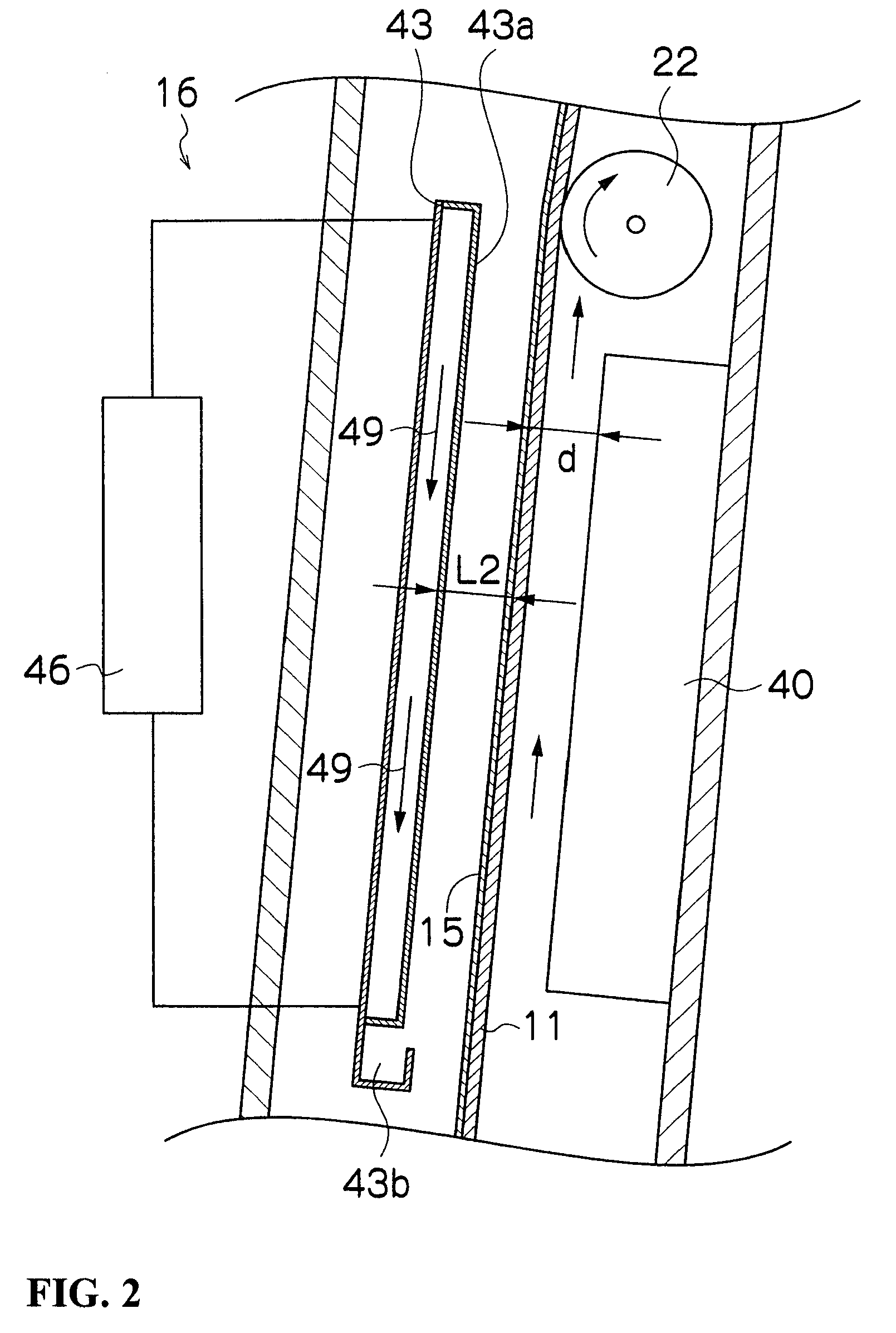
The present invention provides a method and apparatus for drying a coating film that can increase the drying rate without causing unevenness of coating. This is achieved by utilizing both air heat transfer and radiant heat transfer. The ratio of radiant heat transfer to air heat transfer is important and should be between 0.25 and 0.6 to achieve optimal drying. The heater used should be an infrared heater that emits infrared rays with a wavelength of 1 μm or more and has an infrared emissivity of 90% or more. The distance between the heater and the band-shaped flexible substrate should be between 1 mm and 10 mm for optimal air heat transfer. The surface temperature of the heater should be between 80°C and 130°C for optimal heat transfer. The invention also provides an optical film produced using this drying method.

Problems solved by technology

However, conventional methods had a problem in that, when the amount of coating was increased or line speed was increased, drying was not completed in a drying zone to thereby cause a drying unevenness failure.

Method used


Image

  • Method and apparatus for drying coating film and method for producing optical film
  • Method and apparatus for drying coating film and method for producing optical film
  • Method and apparatus for drying coating film and method for producing optical film

Examples


example 1

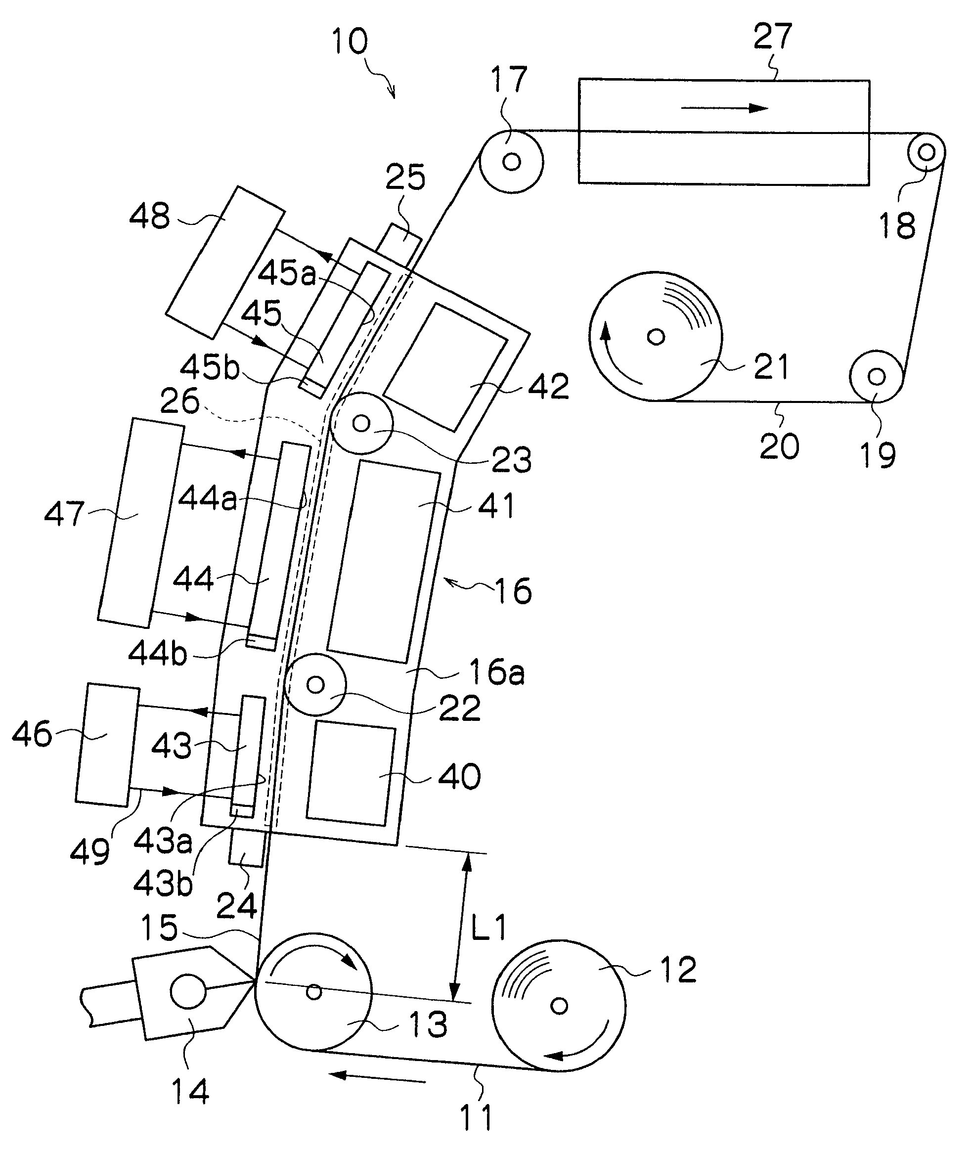
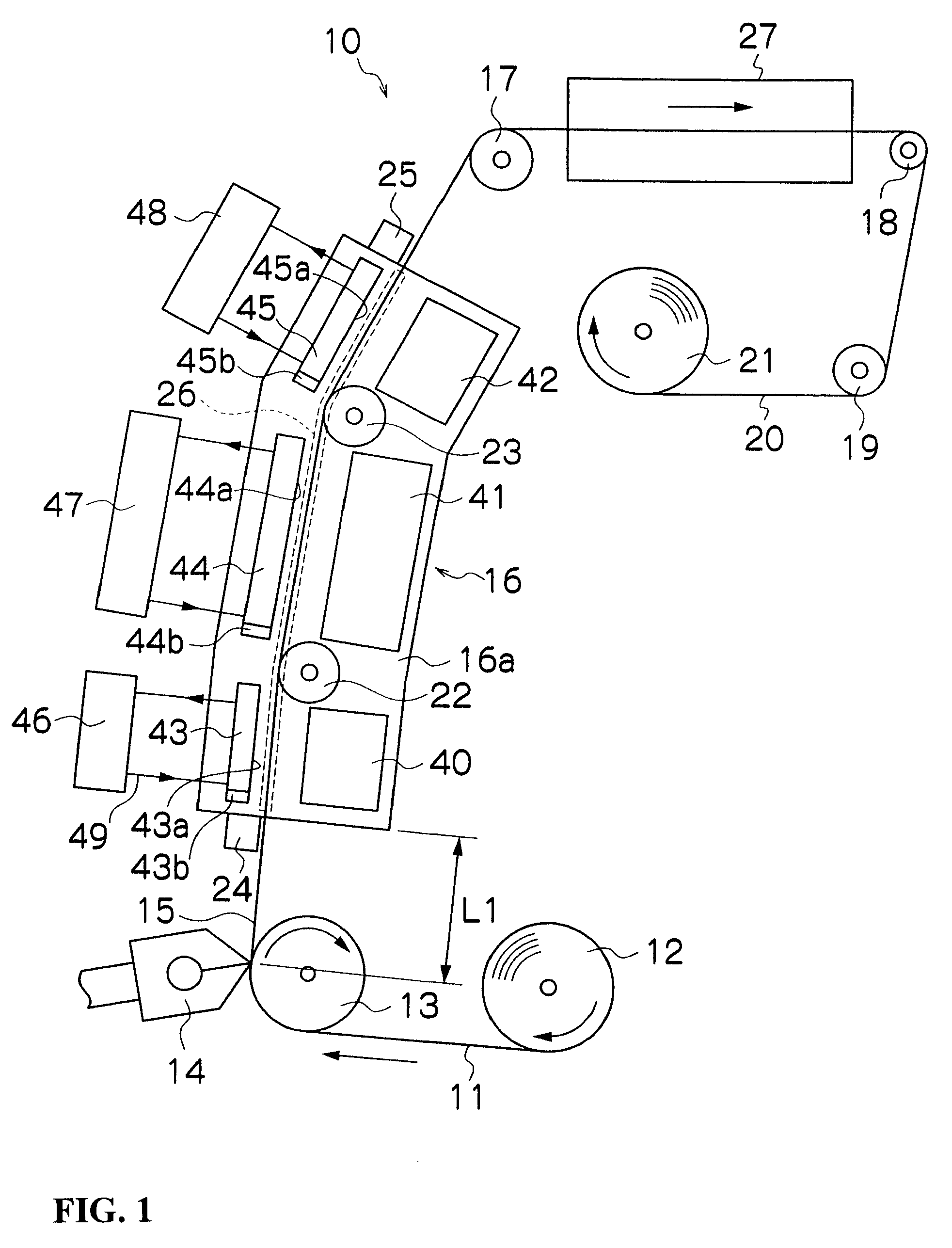
[0070]In the step of drying a coating layer in a production line of an optical compensation sheet, there was provided, at a running position immediately after coating, a dryer 16 covered with a casing to prevent air disturbance in the vicinity of the coated surface, and heating conditions in the dryer 16 suitable for producing the optical compensation sheet was studied.

[0071]In the production line, the optical compensation sheet is produced, for example, according to the following steps:[0072]1) the step of feeding a transparent film;[0073]2) the step of forming an alignment film-forming resin layer, wherein a coating liquid containing an alignment film-forming resin is applied to a surface of a transparent film and dried;[0074]3) a rubbing step of subjecting the surface of the resin layer to rubbing treatment to form an alignment film on the transparent film with the alignment film-forming resin layer formed on the surface thereof;[0075]4) the step of coating a liquid crystalline d...


PUM

PropertyMeasurementUnit
infrared emissivityaaaaaaaaaa
wavelengthaaaaaaaaaa

Abstract

The present invention provides a method for drying a coating film comprising drying a coating film of an organic solvent-containing coating liquid applied to a running band-shaped flexible substrate, the drying method comprising the steps of: providing a heater at a position opposed to the band-shaped flexible substrate at a running position immediately after coating; and heating the band-shaped flexible substrate by the heater; wherein when TW( ° C.) denotes the surface temperature of the band-shaped flexible substrate; TH( ° C.) denotes the surface temperature of the heater; λ(W / m·K) denotes the heat-transfer coefficient of air; d(m) denotes the distance between the heater and the band-shaped flexible substrate (web); η denotes the efficiency of heat transfer; and σ denotes the Stefan-Boltzmann constant (5.670×10⁻⁸ W / m2K4), the ratio of radiant heat transfer represented by QR / (QR+QC) is 0.25 or more and 0.6 or less, wherein QC and QR are represented by the following equations, respectively: QC=λ / d·(TH−TW) where QC denotes heat transfer by air, and QR=η{(TH+273)4−(TW+273)4} where QR denotes heat transfer by radiant.

Description

BACKGROUND OF THE INVENTION[0001]1. Field of the Invention[0002]The present invention relates to a method and an apparatus for drying a coating film, particularly to a method and an apparatus for drying the surface of a long and wide coating film formed by applying various liquid compositions to a continuously running band-shaped flexible substrate (hereinafter referred to as “web”) and a method for producing an optical film.[0003]2. Description of the Related Art[0004]As a method and an apparatus for drying the surface of a long and wide coating film formed by applying various liquid compositions to a continuously running web, there is known a drying method in which a non-coated surface of the web is supported by a roll and the web is dried by blowing air onto a coated surface from an air nozzle; or a non-contact air floating drying method in which a web is dried by blowing air onto both a coated surface and a non-coated surface of the web from air nozzles in a state where the web ...

Claims


Application Information

Patent Timeline
Patent Type & Authority Patents(United States)
IPC IPC(8): F26B3/30
CPCF26B3/283F26B3/30F26B13/10F26B25/006B05C9/14
Inventor SONOBE, MASAKIYAHIRO, TAKASHI
Owner FUJIFILM CORP
Learn More