Supercharge Your Innovation With Domain-Expert AI Agents!

Method and system for supporting multiple services with a subscriber optical interface located outside a subscriber's premises

a subscriber optical interface and subscriber technology, applied in the field of video, voice and data communications, to achieve the effect of reducing or minimizing hardware, reducing the size and complexity of a set-top box, and avoiding sacrificing a range of services availabl

Inactive Publication Date: 2009-05-05
ARRIS SOLUTIONS
View PDF232 Cites 39 Cited by
  • Summary
  • Abstract
  • Description
  • Claims
  • Application Information

AI Technical Summary

Benefits of technology

"The present invention is a system and method for tuning a broadcast receiver, such as a television set, using a subscriber optical interface (SOI) that can be located outside of a subscriber's premises. This allows for a reduction or minimization of hardware located inside the subscriber's premises, which can be beneficial for service providers. The SOI can be connected to a control interface located inside the premises, which can relay signals from a remote controller to the SOI. The control interface can include a wireless transceiver, infrared transmitter / receiver, or RF transmitter / receiver. The invention can also allow for the transmission of electronic program guides and live broadcasts to the television set. Overall, the invention provides a way to tune a broadcast receiver without sacrificing the complexity and cost of equipment inside the subscriber's premises."

Problems solved by technology

It is recognized that set-top boxes are frequently needed because most conventional television sets, at the time of this writing, cannot tune digital channels or Internet Protocol (IP) broadcasts.

Method used


Image

  • Method and system for supporting multiple services with a subscriber optical interface located outside a subscriber's premises
  • Method and system for supporting multiple services with a subscriber optical interface located outside a subscriber's premises
  • Method and system for supporting multiple services with a subscriber optical interface located outside a subscriber's premises

Examples


Embodiment Construction

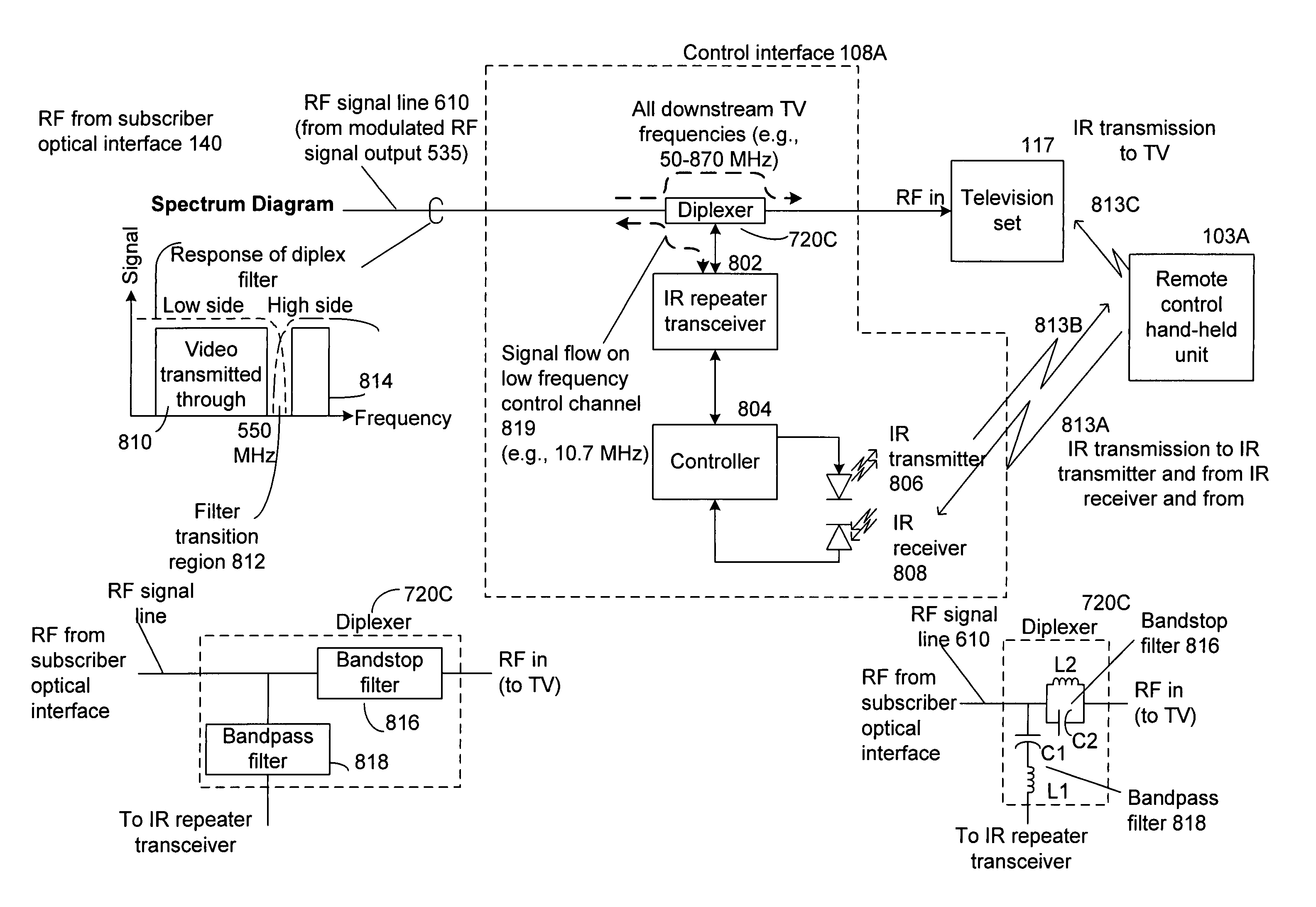
[0068]With the present invention, video signaling processing hardware that is present within the subscriber's premises for tuning video programs can be minimized or reduced without sacrificing a range of services available to a subscriber from a fiber-to-the-home optical network. In other words, the size and complexity of a set-top box can be reduced and in some cases, the set-top box can be eliminated. It is recognized that set-top boxes are frequently needed because most conventional television sets, at the time of this writing, cannot tune digital channels or Internet Protocol (IP) broadcasts.

[0069]Some components of the present invention may be physically located in a subscriber's premises but would have the main purpose of relaying information back to the subscriber optical interface that is physically located external to a subscriber's premises such as a house. In this way, a service provider can update or maintain more complex network equipment that is accessible on the outsi...


PUM


Abstract

A system and method for tuning a broadcast receiver such as a television set with a subscriber optical interface (SOI) that can be located outside a subscriber's premises and can be adjacent to the subscriber's premises. For example, a subscriber optical interface can be mounted on a side of a home which converts optical data and optical video signals received from an optical waveguide to electrical signals. Because of the hardware contained in the subscriber optical interface, any video processing hardware that is present within the subscriber's premises for tuning video programs can be reduced or substantially eliminated without sacrificing a range of services available to a subscriber from a fiber-to-the-home optical network.

Description

STATEMENT AND PRIORITY REGARDING RELATED APPLICATIONS[0001]The present application is a continuation-in-part of non-provisional patent application entitled, “System and Method for Communicating Optical Signals Between A Data Service Provider and Subscribers,” filed on Jul. 5, 2001 now U.S. Pat. No. 6,973,271 and assigned U.S. application Ser. No. 09 / 899,410; and the present application claims priority to provisional patent application entitled, “Home Interface Terminal for Multiple Services,” filed on Dec. 18, 2002 and assigned U.S. application Ser. No. 60 / 433,984. The entire contents of both the Non-provisional and Provisional applications are hereby incorporated by reference.TECHNICAL FIELD[0002]The present invention relates to video, voice, and data communications. More particularly, the present invention relates to a fiber-to-the-home (FTTH) system that includes a subscriber optical interface with increased functionality that converts optical signals into the electrical domain f...

Claims


Application Information

Patent Timeline
Patent Type & Authority Patents(United States)
IPC IPC(8): H04B10/00H04B10/272H04J14/02H04N7/173H04N7/22H04Q11/00
CPCH04J14/0282H04N7/17309H04N7/22H04Q11/0067H04J14/0232H04J14/0247H04J14/0252H04J14/0226H04J14/028H04J14/0286H04Q11/0071H04N21/6118H04N21/6168
Inventor FARMER, JAMES O.THOMAS, STEPHEN A.
Owner ARRIS SOLUTIONS
Features
  • R&D
  • Intellectual Property
  • Life Sciences
  • Materials
  • Tech Scout
  • Unparalleled Data Quality
  • Higher Quality Content
  • 60% Fewer Hallucinations
Learn More