
Electrical junction box for a solar cell module

a solar cell module and electric junction technology, applied in the direction of electrically conductive connections, photovoltaics, coupling device connections, etc., can solve the problems of reducing output, affecting the overall operation of the solar cell module, and the entire module cannot deliver current. , to achieve the effect of simple and reliable connection of thin conductor strips

Inactive Publication Date: 2009-05-12
GUNTHER SPELSBERG GMBH CO
View PDF11 Cites 32 Cited by
  • Summary
  • Abstract
  • Description
  • Claims
  • Application Information

AI Technical Summary

Benefits of technology

This design simplifies the connection process, reduces effort, and enhances reliability by allowing flexible arrangement and insertion of conductor strips and supply leads, preventing damage from partial shading and reducing power loss, while maintaining module functionality.

Problems solved by technology

However, a problem can arise when a solar cell module is partially shadowed, therefore a solar cell or individual solar cells of the solar cell module receive less or no solar radiation at all.
In contrast to shadowing of the solar module uniformly over its entire surface, which leads only to a reduction in output, the following problem arises with partial shadowing: A common current flows through the series-connected solar cells of the solar cell module, each individual solar cell with its respective voltage contributing to the total voltage of the solar cell module.
However, this means that the entire module can no longer deliver current, so that the overall operation of the solar cell module is adversely affected.
If the voltage on the shadowed solar cell is greater than its blocking voltage, a breakdown occurs in the solar cell, and thus, the solar cell is permanently damaged.
Even if the solar cell should not be damaged by the breakdown, a large power loss is converted in the shadowed solar cell so that the shadowed solar cell heats up.
This heating can also lead to damage to the shadowed solar cell and to the solar cells adjacent to it.
This results in that a shadowed solar cell no longer supplies a portion to the overall voltage of the solar cell module, but the current flow is nevertheless maintained.
In any case, this procedure is very complex and time-consuming, and connection faults cannot be easily avoided.
Moreover, in the known junction box, it is disadvantageous that, based on the limited external dimensions of the housing generally within the junction box, the electrical and / or electronic means and the connection device must be located very near one another.
For this reason, only a very small free space is available for connecting the conductor strips; this makes connection difficult.

Method used


Image

  • Electrical junction box for a solar cell module
  • Electrical junction box for a solar cell module
  • Electrical junction box for a solar cell module

Examples


Embodiment Construction

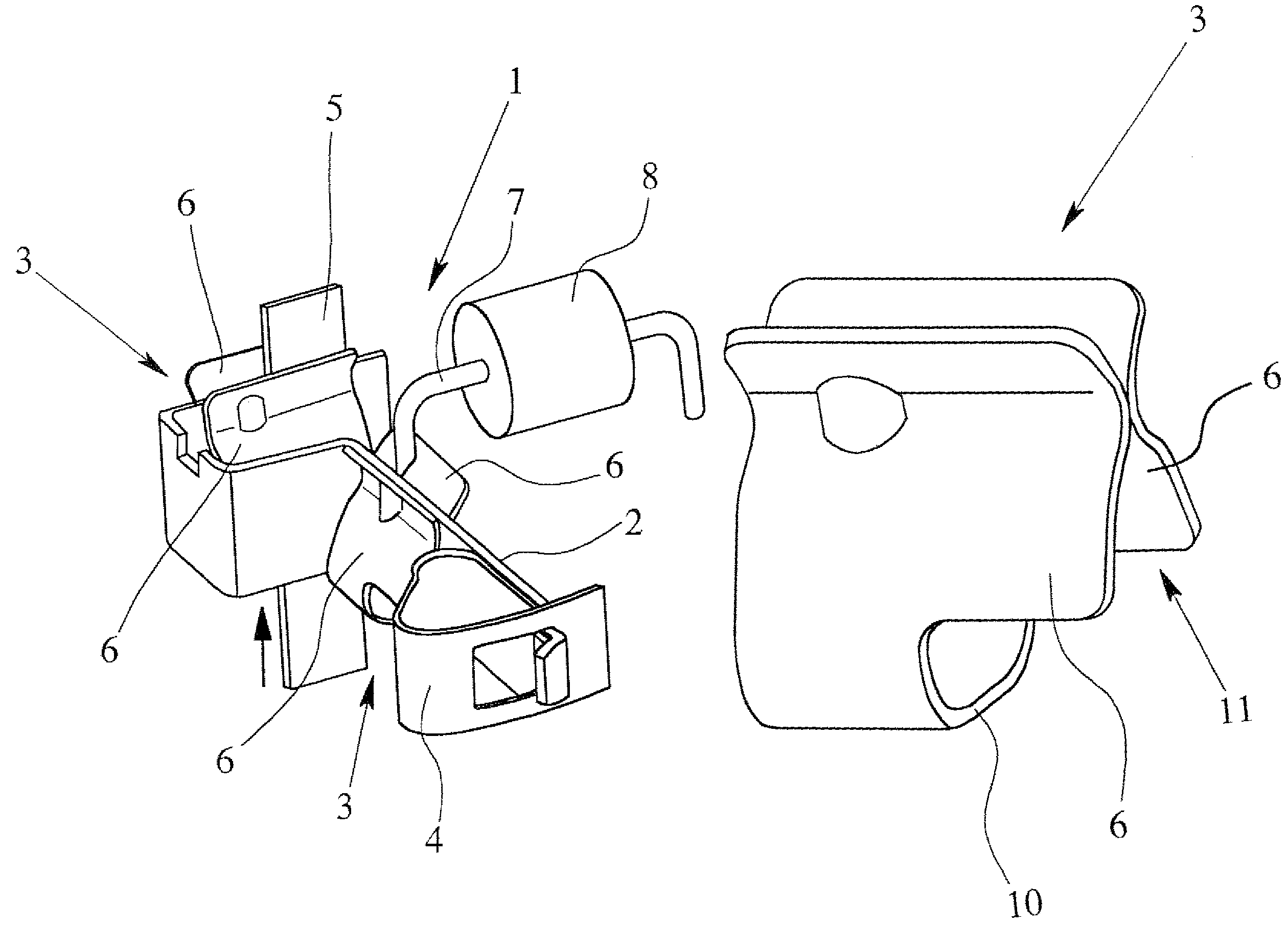
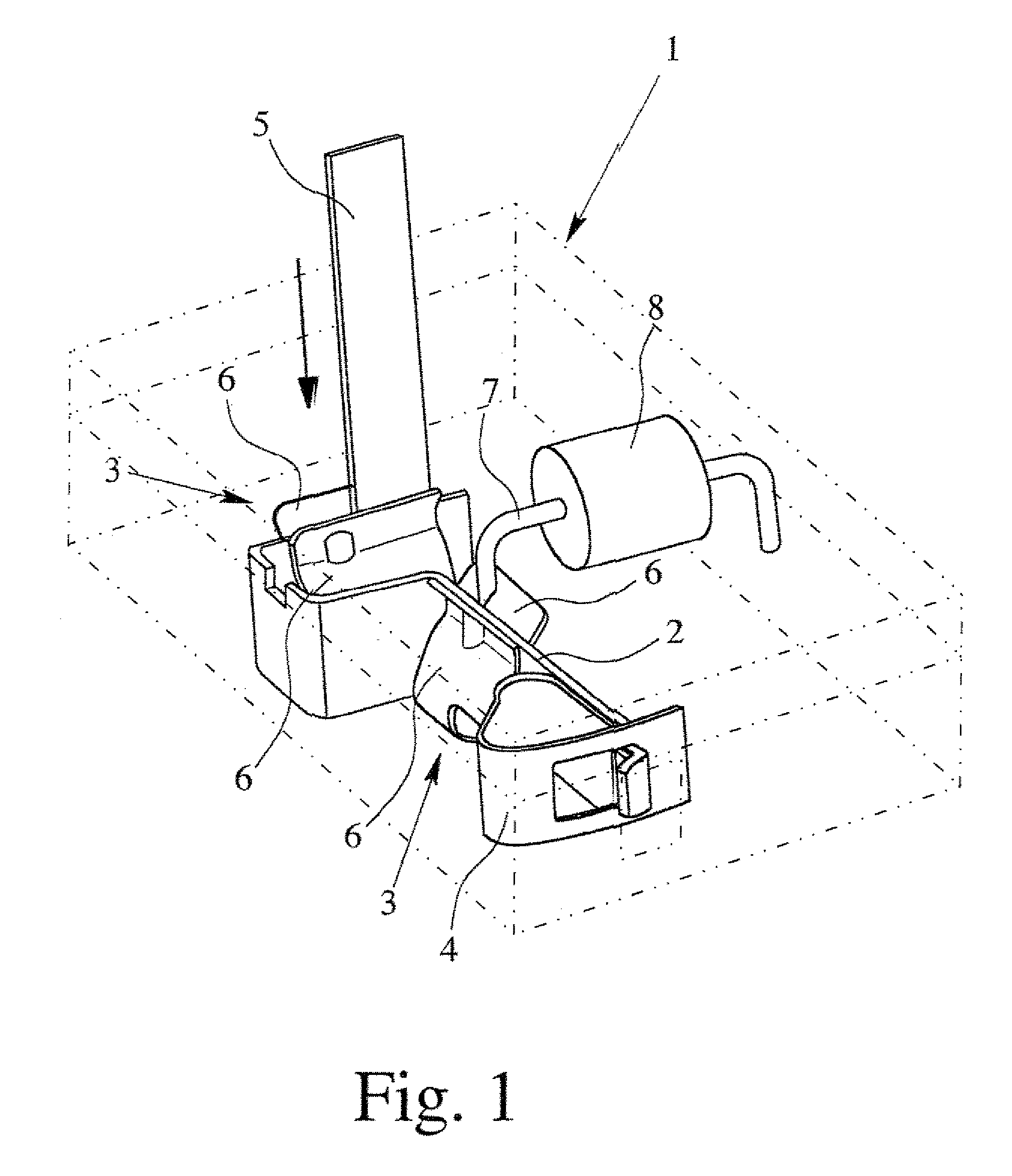
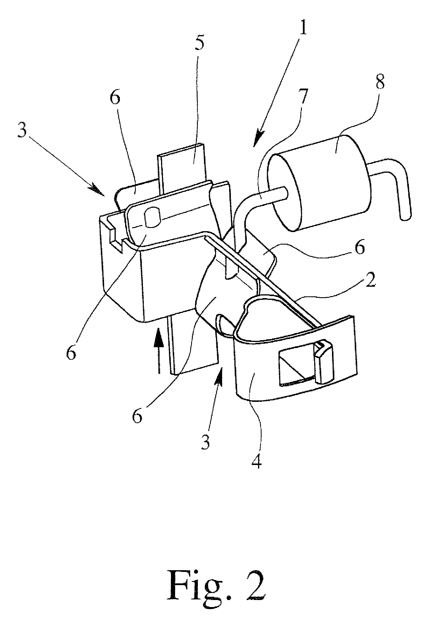
[0031]In FIG. 1, a preferred embodiment of a connection device 1 is shown which can be used to connect a junction box in accordance with the invention to a solar cell module the housing of the junction box being only schematically represented in phantom outline since the construction of the housing itself, apart from the provision of openings on additional sides. can be of any suitable construction and configuration known for junction boxes of this type. The connection device 1 has a current bar 2 and two clamping means 3 which are clamped onto the current bar 2. Fundamentally, more than two clamping means 3 can also be clamped onto the current bar 2. Moreover, the current bar 2 has a terminal 4 on a free end, and in this case, a tension spring terminal. In the installed state, the connection device 1 is located within the electrical junction box and is connected to the solar cell module via thin conductor strips 5.

[0032]In order to enable simple and reliable connection of the thin ...


PUM


Abstract

An electrical junction box for a solar cell module of solar cells which are connected with thin conductor strips, with a housing and electrical and / or electronic devices provided in the housing, and at least one electrical connection device (1) which has at least one terminal (3) and which is provided in the housing. The clamping mechanism (3) for producing clamping contact is made and arranged such that at least one thin conductor strip (5) routed out of the solar cell module can be inserted into the clamping mechanism in two different opposing entry directions. Thus, simple and reliable connection of thin conductor strips (5) routed out of the solar cell module can be guaranteed.

Description

BACKGROUND OF THE INVENTION[0001]1. Field of the Invention[0002]The invention relates to an electrical junction box for a solar cell module of solar cells which are connected with thin conductor strips, with a housing and electrical and / or electronic means provided in the housing, and at least one electrical connection device which has at least one terminal means and which is provided in the housing.[0003]2. Description of Related Art[0004]Since the output voltage of individual solar cells is generally too low to operate electrical devices, such as household appliances or similar devices, generally, several solar cells are interconnected to form solar cell modules. In this regard, on the one hand, there is the possibility of series connection of the solar cells, and on the other, the possibility of parallel connection of the solar cells in the solar cell module. The individual currents of the solar cells are added to one another to form the overall current by parallel connection of ...

Claims


Application Information

Patent Timeline
Patent Type & Authority Patents(United States)
IPC IPC(8): H01R4/24
CPCH02S40/34H01R4/4818H01R13/113Y02E10/50H01R4/4821H01R4/485H01R4/4816
Inventor NIELECK, UDOQUARDT, DIRKWASSERFUHR, FRIEDELZBOROWSKI, ZBIGNIEWSCHMIDT, WIELANDSPELSBERG, HOLGER
Owner GUNTHER SPELSBERG GMBH CO
Learn More