Motor drive device

a three-phase brushless, motor technology, applied in the direction of motor/generator/converter stopper, electronic commutator, dynamo-electric converter control, etc., can solve the problems of insufficient phase characteristics control, pulse current rise, and difficult to accurately read peak pulse current flow, etc., to achieve the effect of reducing the number of motors, and improving the reliability of neutral point difference voltag

Active Publication Date: 2009-05-12
COLLABO INNOVATIONS INC
View PDF10 Cites 29 Cited by
  • Summary
  • Abstract
  • Description
  • Claims
  • Application Information

AI Technical Summary

Benefits of technology

[0023]The motor drive device of the present invention applies a search pulse for a specific range to compare the neutral point difference voltage with a specific value to determine the rotor position. The likelihood of immediately knowing the rotor position from the selected phase is therefore constant. The rotor can therefore be started by immediately energizing the appropriate drive phase after detecting the rotor position. The invention thus enables applying a torque signal to start the motor without determining the rotor position after selectively energizing specific phases. The search and start mode is thus shortened and the motor can be started more quickly. The reliability of the neutral point difference voltage is also improved and the rotor position can be accurately detected because the neutral point difference voltage is detected from the search pulse in a specific range.
[0024]In the search and start mode that produces rotational speed sufficient to start the motor, rotor position information that does not include the back-EMF voltage can be detected at the neutral point difference voltage, and the search and start mode can therefore be reliably executed. A sensorless motor can therefore be reliably and quickly started because the back-EMF voltage mode is enabled after the search and start mode. This control configuration can also be implemented easily at low cost.

Problems solved by technology

Sensorless drive technology that does not require a rotor position sensor has also been developed due to concerns about reliability, cost, and the environment.
A problem with EP Patent Application Publication No. 0251785 is that it is difficult to accurately read the peak pulse current flow when the rotor position search pulse is applied.
The technology taught in EP Patent Application Publication No. 0251785 therefore is difficult to use in inexpensive motors having insufficient phase characteristics control.
Furthermore, the pulse current rises in motors in which the coil inductance is reduced for high speed performance, and the current required to achieve a desired pulse current peak difference is extreme.
A problem with U.S. Patent Application Publication No. 2004 / 0056628 is that there is a range where the rotor position cannot be detected.
If the motor is stopped in this range when the motor starts, it may not be possible to start the motor no matter how many times the rotor position detection pulse is applied because the motor may be stopped where the rotor position cannot be detected.
Furthermore, when the rotor position cannot be correctly detected, reversing or loss of synchronization may occur even if the back-EMF voltage mode is entered from the initial rotor position detection process.

Method used


Image

  • Motor drive device
  • Motor drive device
  • Motor drive device

Examples


embodiment 1

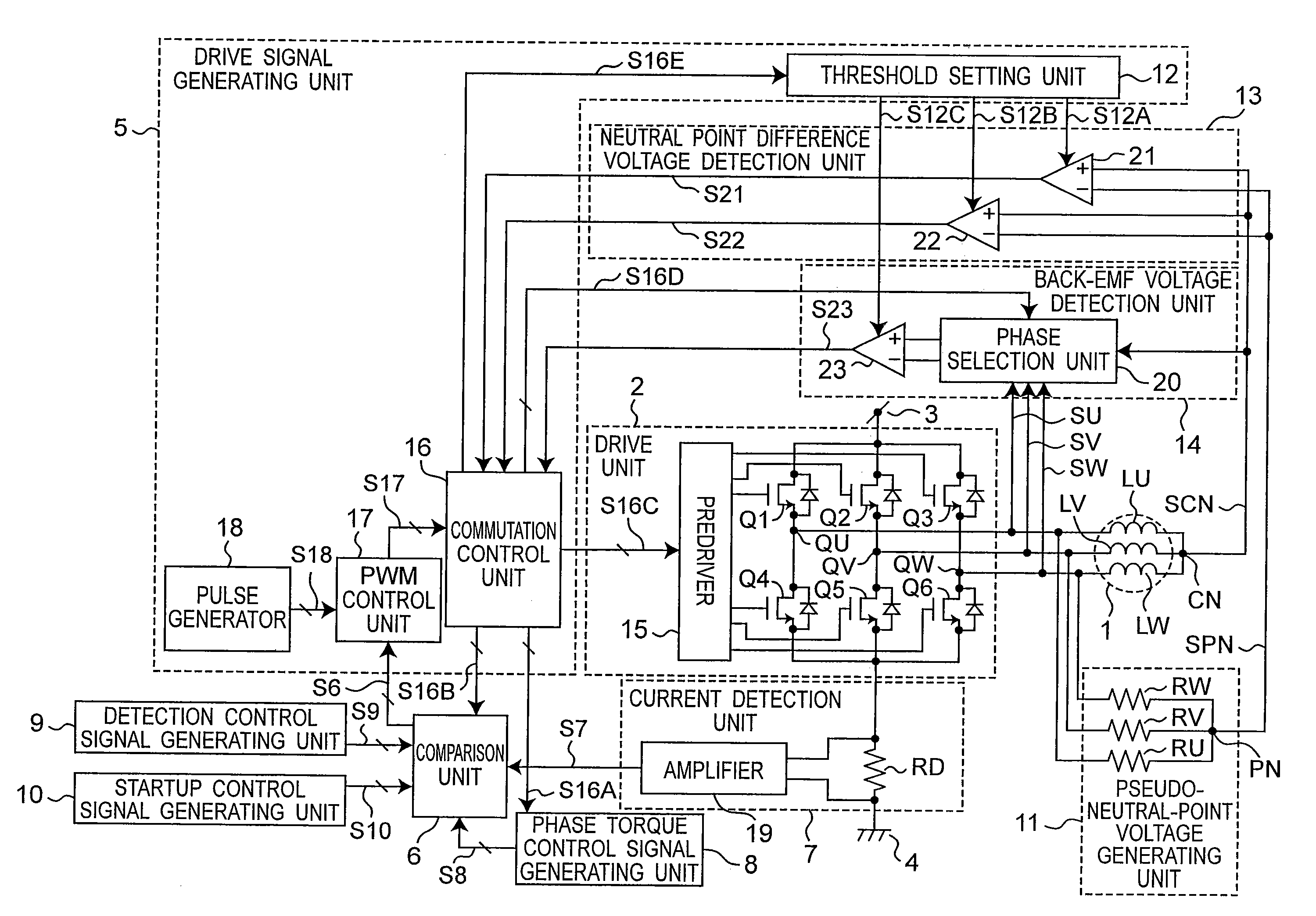
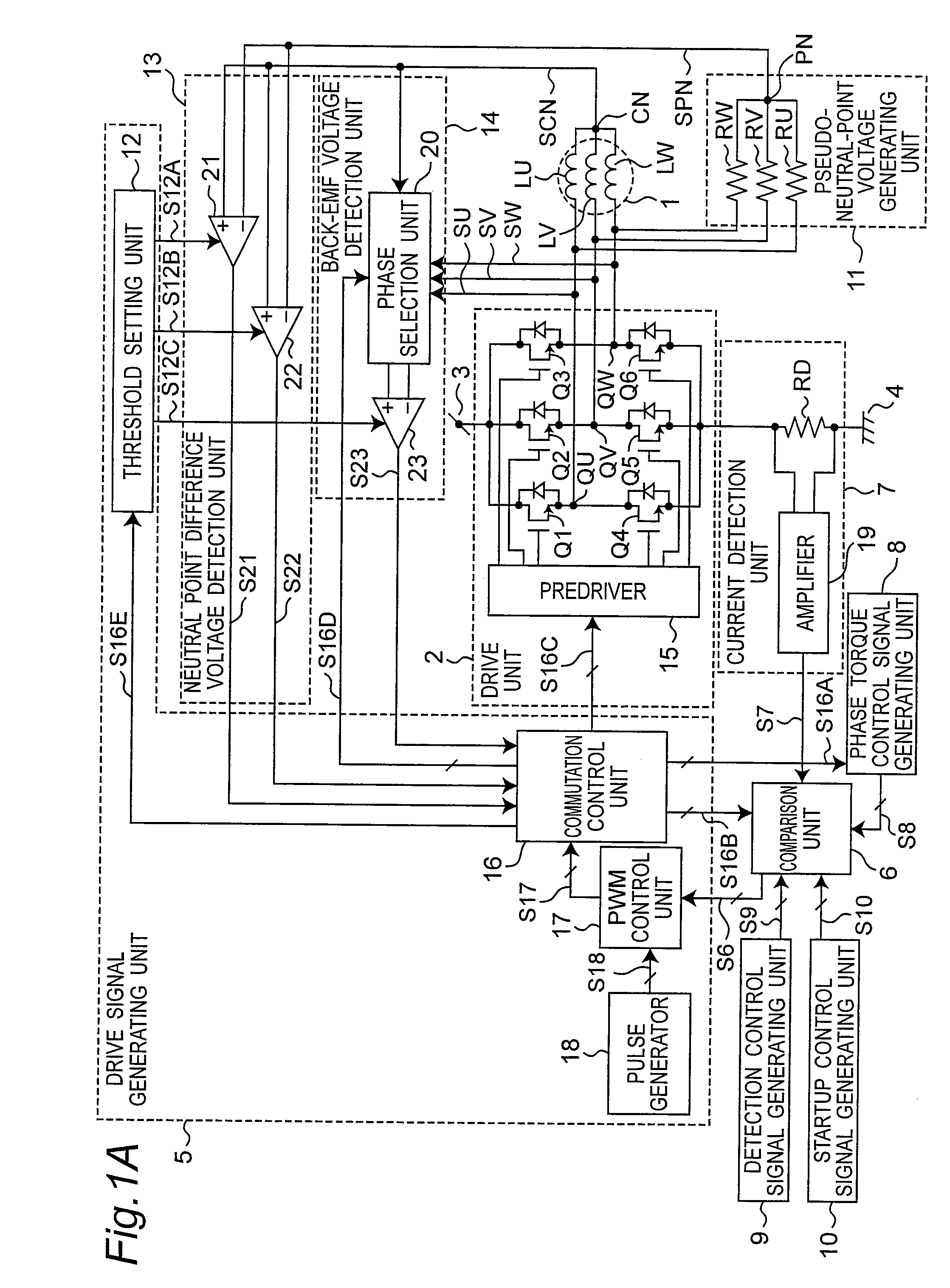
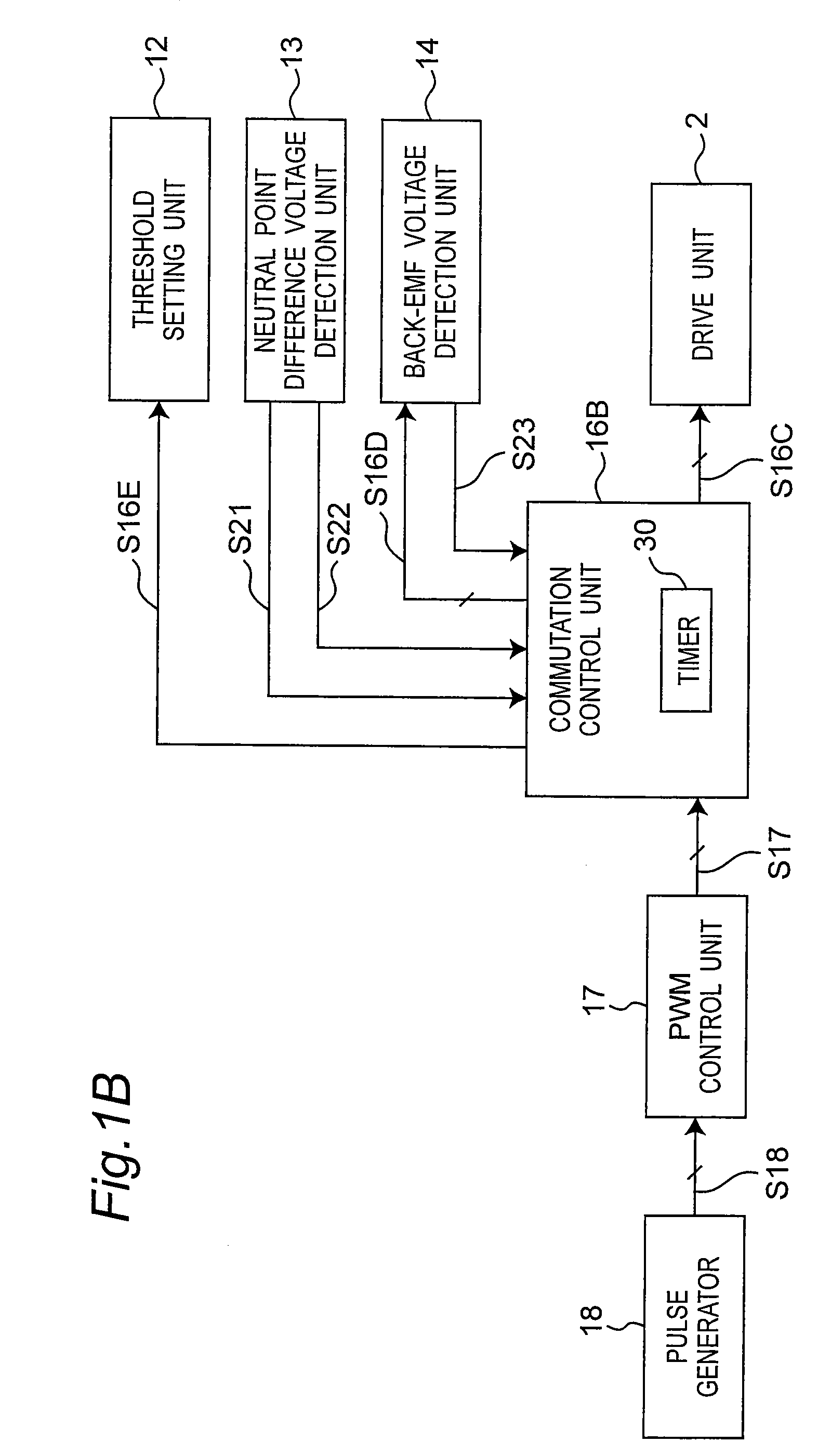
[0064]FIG. 1A is a circuit block diagram of a motor drive device according to a first embodiment of the invention. The motor drive device shown in FIG. 1A has a motor 1, a drive unit 2, a drive signal generating unit 5, a comparison unit 6, a current detection unit 7, a phase torque control signal generating unit 8, a detection control signal generating unit 9, a startup control signal generating unit 10, a pseudo-neutral-point voltage generating unit 11, a neutral point difference voltage detection unit 13, and a back electromotive force (back-EMF) voltage detection unit 14.

[0065]The motor 1 has a three-phase fixed stator and a rotor that rotates around the stator. A three-phase motor 1 is used as the motor in this first embodiment of the invention, but the invention can be applied to any N-phase motor where N is an integer of two or more. The U-phase motor winding LU, V-phase motor winding LV, and W-phase motor winding LW are connected in common at neutral point CN, and the other ...

second embodiment

[0443]The first embodiment has been described using two energized phases. This second embodiment of the invention uses three energized phases and is described below with particular reference to the difference with the first embodiment. Other aspects of the arrangement, operation, and effect are the same as in the first embodiment above.

[0444]FIG. 20 shows the circuit arrangement of the motor drive device according to a second embodiment of the invention. The motor drive device shown in FIG. 20 has a motor 1, a drive unit 2, a drive signal generating unit 5, a comparison unit 6, a current detection unit 7, a phase torque control signal generating unit 8, a detection control signal generating unit 9, a startup control signal generating unit 10, a pseudo-neutral-point voltage generating unit 11, a neutral point difference voltage detection unit 13A, and a back-EMF voltage detection unit 14A.

[0445]The motor 1 has a three-phase fixed stator and a rotor that rotates around the stator. The...


PUM


Abstract

Problems with accuracy reading position detection signal peaks and minute phase differences in the detection current make motor drive control easily susceptible to differences in motor characteristics. The rotor position is determined based on whether or not a neutral point difference voltage, which is the difference voltage between the neutral point voltage and the pseudo-neutral-point voltage when the motor phases are selectively energized, exceeds a specific threshold value. The phase energized to start the motor is determined based on this determination and the motor is energized accordingly to start. Instead of switching directly from the search step at the initial rotor position to the back-EMF voltage mode, a search and start mode that creates initial rotor speed sufficient to start the motor is executed before entering the back-EMF voltage mode.

Description

BACKGROUND OF THE INVENTION[0001]1. Field of Invention[0002]The present invention relates to a three-phase brushless motor drive device enabling consistently starting quickly without requiring a rotor position sensor.[0003]2. Description of Related Art[0004]Brushless motors use a suitable number of windings in the stator winding to which current is supplied to apply a consistent amount of torque to the rotor. This requires knowing the electrical phase position of the rotor relative to the stator. Various kinds of rotor position sensors are used for knowing this relative phase position. Sensorless drive technology that does not require a rotor position sensor has also been developed due to concerns about reliability, cost, and the environment. Sensorless drive technologies generally detect the rotor position by reading the back electromotive force (back-EMF) voltage produced in the stator winding when the rotor is turning. However, because this back-EMF voltage is not produced when t...

Claims


Application Information

Patent Timeline
Patent Type & Authority Patents(United States)
IPC IPC(8): H02P6/18H02P6/06H02P6/08H02P6/182H02P6/21
CPCH02P6/182H02P6/205H02P6/21
Inventor FUKAMIZU, SHINGOYAMAMOTO, YASUNORIKUROSHIMA, SHINICHI
Owner COLLABO INNOVATIONS INC
Why Eureka
Try Eureka