Eyeshot detection device using distance image sensor

a detection device and distance image technology, applied in the field of eyeshot detection devices using distance image sensors, can solve the problems of cumbersome camera calibration of stereo cameras, and the inability to accurately measure the distance to the pupil using a tof (time of flight) method using such an ultrasonic wave, and achieve the effect of responding quickly

Active Publication Date: 2009-05-19
NAT UNIV CORP SHIZUOKA UNIV
View PDF14 Cites 16 Cited by
  • Summary
  • Abstract
  • Description
  • Claims
  • Application Information

AI Technical Summary

Problems solved by technology

However, aforementioned methods have problems such as needing at least two cameras, cumbersome camera calibration of stereo cameras.
However, the distance to a pupil cannot be correctly measured by a TOF (Time of flight) method using such an ultrasonic wave, because the ultrasonic wave actually reflects in a wide range around an eye due to problems such as weak directivity of the ultrasonic wave.

Method used


Image

  • Eyeshot detection device using distance image sensor
  • Eyeshot detection device using distance image sensor
  • Eyeshot detection device using distance image sensor

Examples


embodiment

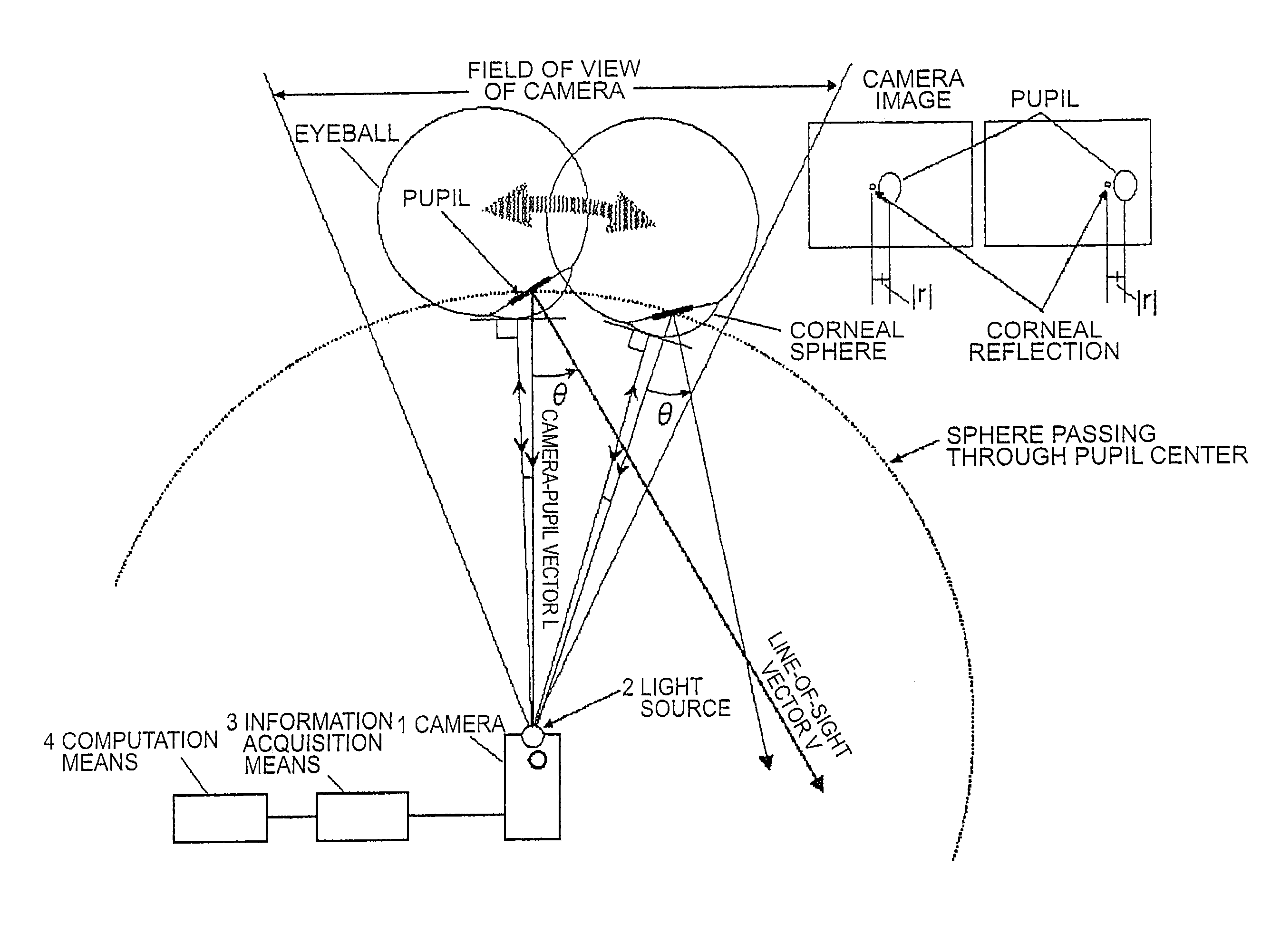
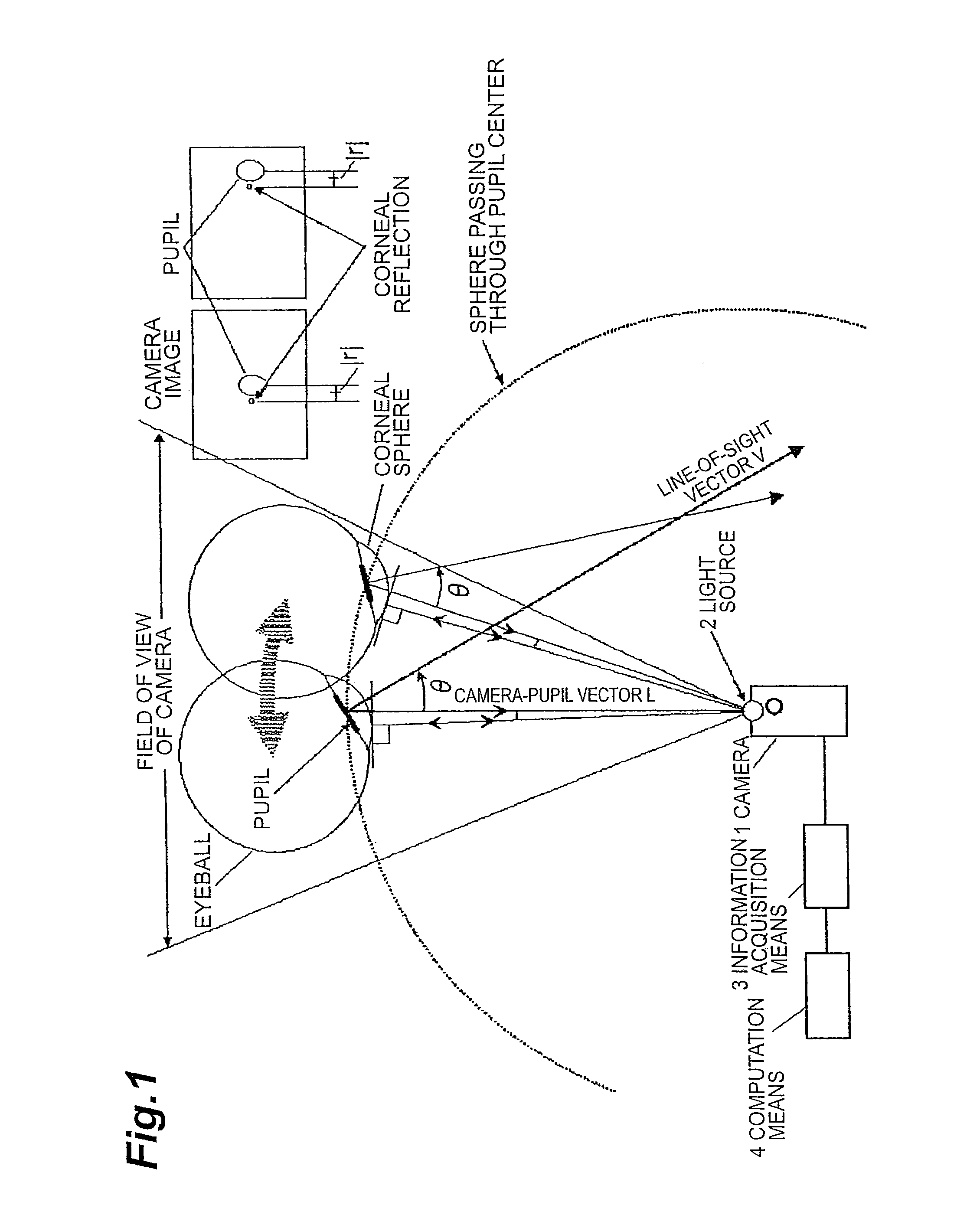
[0025]It is assumed, as shown in FIG. 5, that the camera (1) and the light source (2) are arranged at origin O of the camera coordinate system, which is known in advance, and one or two eyes' image have been taken by the camera. Now, in an eye's image taken as shown in FIG. 6(a), the computation means (4) detects a pupil and corneal reflection based on image processing and determines respective center coordinates. The computation means (4) calculates a size |q| of a vector q connecting from coordinates corresponding to the camera optical axis in the image to the pupil center, an angle η′ formed by the vector and the horizontal axis, and three-dimensional coordinates of the pupil center from a distance L between the camera and pupil center measured by the camera (1). Here, the position angle ξ of the pupil center viewed from the camera (1) is in a monotone increasing relationship to |q| If this relationship can be represented by ξ=g (|q|) using a function g and the function g is know...


PUM


Abstract

An object of the present invention is, when determining a line-of-sight vector of a subject, to identify a three-dimensional position of a pupil center or corneal reflection center thereof. The line-of-sight vector is determined by measuring a distance from a camera to the pupil center or corneal reflection center of the subject using a two-dimensional CMOS distance image sensor by a light time-of-flight method and obtaining position information of the pupil center and corneal reflection center of the subject using the distance image sensor. If a position and a direction of the camera are identified, a camera-pupil center vector is determined from image information of the pupil center of the subject. Since the camera-pupil center distance has been measured, a pupil center position in a three-dimensional space is determined from the above information. Combining this with two line-of-sight vectors determines a position where line-of-sight vectors intersect, or a view-point.

Description

CROSS-REFERENCE TO RELATED APPLICATIONS[0001]This is a continuation-in-part application of application Ser. No. PCT / JP2005 / 002661 filed on Feb. 14, 2005, now pending, and incorporated by reference in its entirety.BACKGROUND OF THE INVENTION[0002]1. Field of the Invention[0003]The present invention relates to a method and a device that correctly detect a line-of-sight direction of a subject without contact.[0004]2. Related Background Art[0005]In order to correctly detect a line-of-sight direction of a subject without contact, information about coordinates of a pupil or an eyeball center in a three-dimensional space and an angle formed by a straight line connecting the coordinates thereof and a camera and a line-of-sight is required. Conventionally, a three-dimensional position of a pupil has been detected by the trigonometric method using two wide angle cameras (See, for example, Patent Document 1) or an eyeball center has been estimated by attaching at least three markers on a face ...

Claims


Application Information

Patent Timeline
Patent Type & Authority Patents(United States)
IPC IPC(8): A61B3/10A61B3/14A61B3/113G01B11/00G01S17/88G02B7/40
CPCA61B3/113G06V40/19
Inventor EBISAWA, YOSHINOBU
Owner NAT UNIV CORP SHIZUOKA UNIV
Why Eureka
Try Eureka