Optical wireless transmission system

a wireless transmission and optical technology, applied in the direction of instruments, optical elements, discharge tubes/lamp details, etc., can solve the problems of increasing the size, difficult to perform high speed transmission, and reducing the total light receiving power, so as to achieve stable high speed data communication

Inactive Publication Date: 2009-05-19
PANASONIC CORP
View PDF4 Cites 6 Cited by
  • Summary
  • Abstract
  • Description
  • Claims
  • Application Information

AI Technical Summary

Benefits of technology

[0023]Therefore, an object of the present invention is to provide an optical wireless transmission system capable of preventing a light beam emitted by a light emitting element from being returned to the light emitting element due to reflection, and from being incident on a light receiving element other than a target light receiving element, so as to realize stable high speed data communication.
[0024]The present invention is directed to an optical wireless transmission system for performing data communication by using a light beam transmitted in free space. In order to attain the object mentioned above, the optical wireless transmission system of the present invention comprises: a transmission terminal having at least one light emission section operable to emit a light beam; a reception terminal having at least one light reception section operable to receive the emitted light beam; and a terminal fixing auxiliary component for allowing the transmission terminal and the reception terminal to be mounted thereon, and fixing the at least one light emission section and the at least one light reception section so as to satisfy a predetermined positional relationship therebetween. Further, when the transmission terminal and the reception terminal are mounted on the terminal fixing auxiliary component, the at least one light emission section and the at least one light reception section are positioned such that the light beam emitted by the at least one light emission section is prevented from being reflected by the at least one light reception section and being returned to the at least one light emission section.
[0028]Preferably, the reception terminal may further include at least one second light emission section operable to emit a light beam, and the transmission terminal may further include at least one second light reception section operable to receive the light beam emitted by the reception terminal. Also in this case, when the transmission terminal and the reception terminal are mounted on the terminal fixing auxiliary component, the at least one second light emission section and the at least one second light reception section may be positioned such that the light beam emitted by the at least one second light emission section is prevented from being reflected by the at least one second light reception section and being returned to the at least one second light emission section.
[0031]According to the present invention, it is possible to prevent a light beam emitted by the light emitting element from being returned to the light emitting element due to reflection. Thus, it is possible to obtain a preferable transmission characteristic in a simplified manner, and realize stable high speed data communications.

Problems solved by technology

However, in an optical wireless transmission system, reduction of the light receiving area of the light receiving element leads to reduction of total light receiving power, and therefore it is difficult to perform high speed transmission.
However, the structure shown in FIG. 16 is disadvantageous in that the numbers of light sources and light receiving elements are increased, and therefore mounting areas of the light sources and the light receiving elements are increased, thereby increasing the sizes of the collimator lens 34 and the collecting lens 39.
Therefore, a returned reflected light is incident on the light emitting element array 33, which leads to unstable operation of the light emitting element array 33.
The light having been repeatedly reflected results in delayed signals.
Therefore, the higher a data rate is, the larger this problem is.
However, when the LED 54 and the LED 55 are positioned close to each other so as to attain a purpose described above, emission intensity density of the light beam is increased, and therefore it is necessary to reduce an output power of each LED or reduce the emission intensity density of the light beam by using a diffuser or the like so as to satisfy eye-safe conditions, so that it is not easy to simply obtain an output signal of a high intensity.
As described above, the conventional optical wireless transmission system disclosed in Patent Document 2 is disadvantageous in that, while an increased number of components, such as an arithmetic circuit for noise cancellation and the increased number of light sources, that is, two light sources of different wavelengths, are provided as compared to the numbers of light sources and components of a typical optical wireless transmission system, a data transmission speed is not sufficiently enhanced.

Method used


Image

  • Optical wireless transmission system
  • Optical wireless transmission system
  • Optical wireless transmission system

Examples


first embodiment

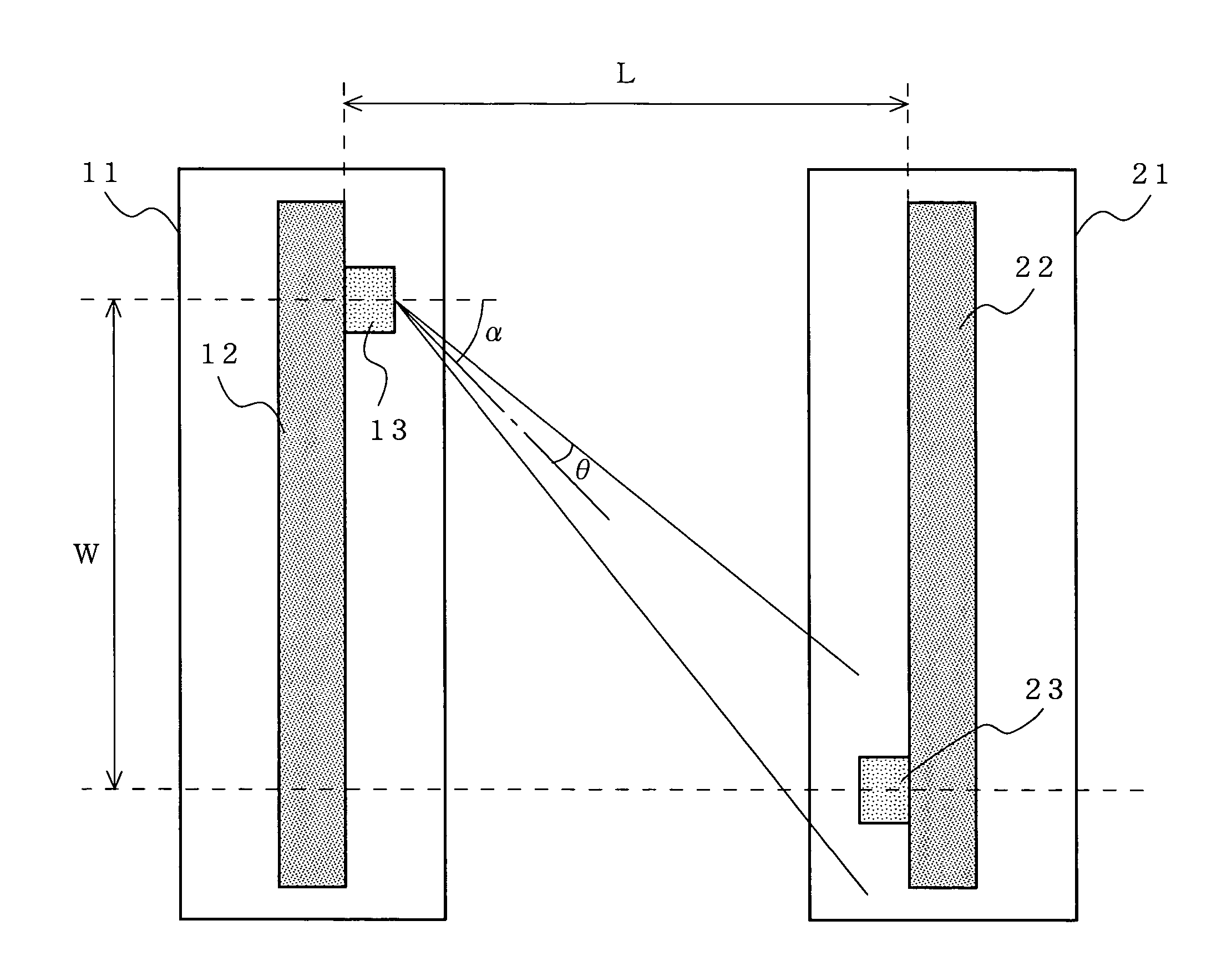
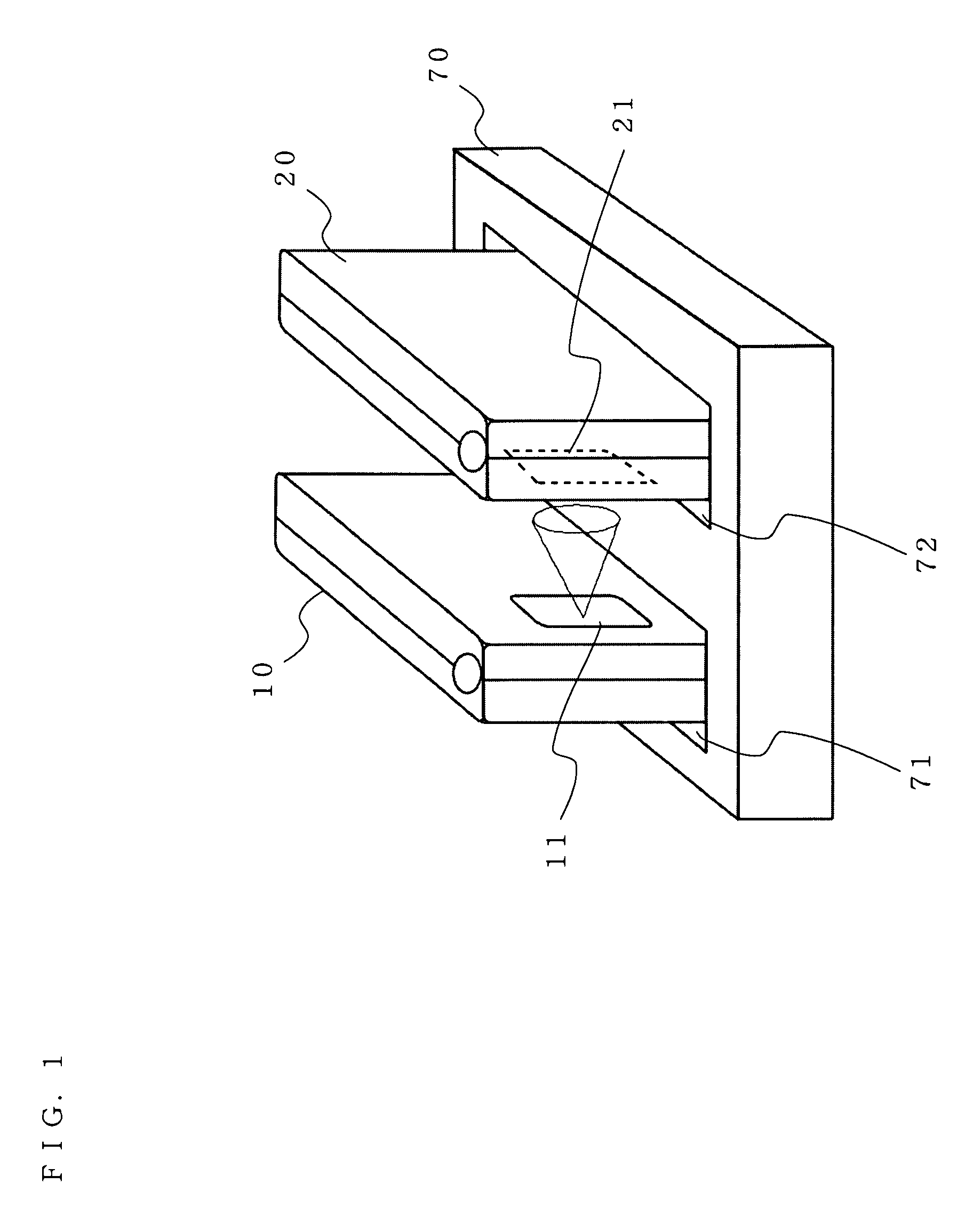
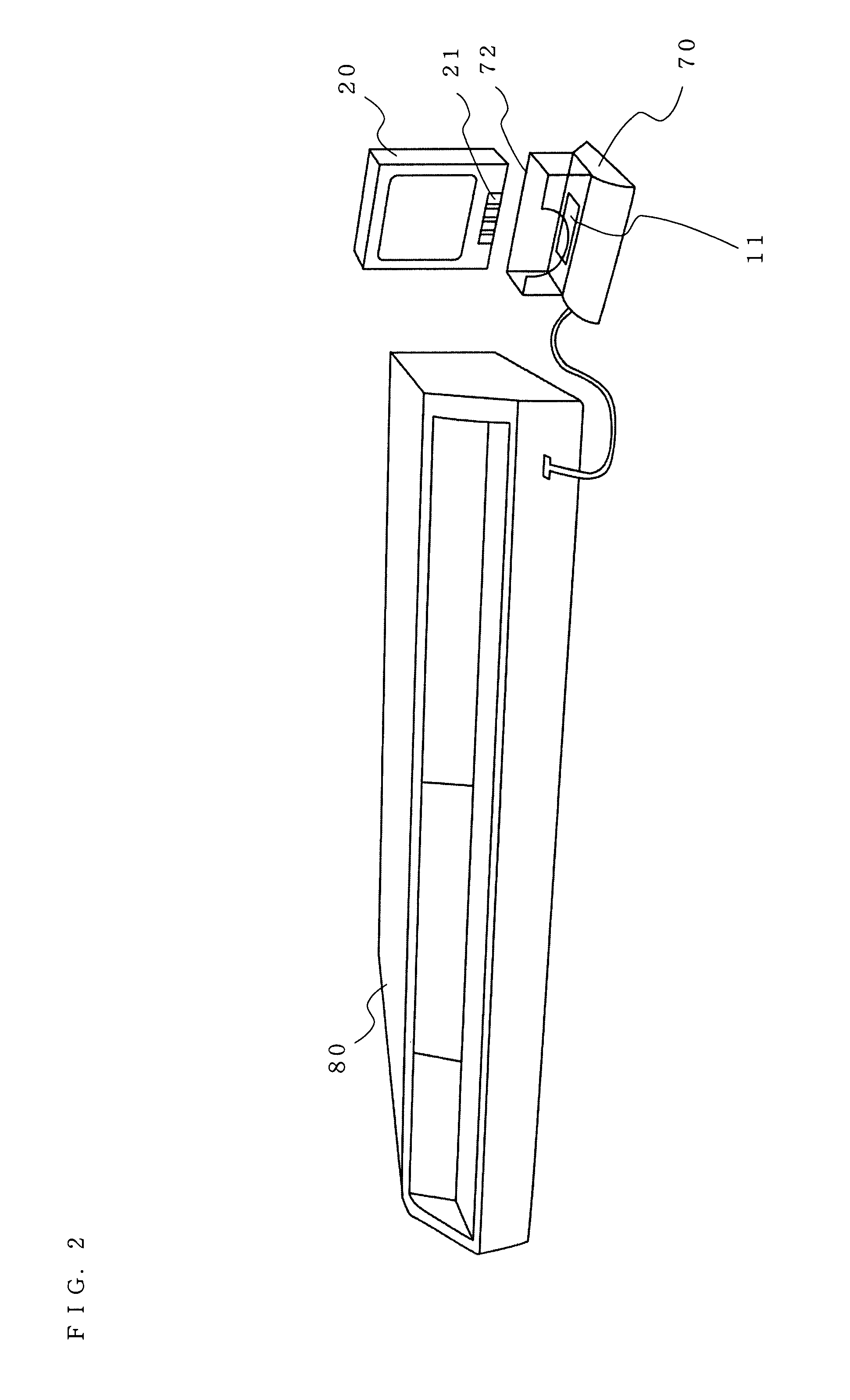
[0053]FIG. 3 is a perspective view illustrating the optical wireless transmission system according to a first embodiment of the present invention. FIG. 4 is a cross-sectional view along lines A-A illustrating the optical wireless transmission system shown in FIG. 3. As shown in FIGS. 3 and 4, the optical transmission section 11 of the transmission terminal 10 has a light emission section 13 provided on a mounting substrate 12. The optical reception section 21 of the reception terminal 20 has a light reception section 23 provided on a mounting substrate 22.

[0054]The light emission section 13, including a light emitting element such as a semiconductor laser, emits a light beam based on communication data. The light reception section 23, including a light receiving element such as a photodiode, receives the light beam emitted by the light emission section 13. According to the present invention, the light emission section 13 and the light reception section 23 are positioned and an emiss...

example 1

(1) Structure Example 1

[0059]In structure example 1, the light emitting element 14 corresponding to the light emission section 13 is previously tilted with respect to the mounting substrate 12, as shown in FIG. 5. This structure allows the illumination direction of the light beam to be easily changed. When the mounted light emitting element 14 is not fixed in a stable manner, a component for supporting the light emitting element 14 may be additionally provided.

example 2

(2) Structure Example 2

[0060]In structure example 2, the light emitting element 14 is mounted on the mounting substrate 12 in a normal state, and an optical fiber 15 is connected to the light emitting element 14 so as to be tilted with respect to the light emitting element 14, as shown in FIG. 6. This structure allows the illumination direction to be easily changed. A component for supporting the optical fiber 15 may be additionally provided such that the optical fiber 15 is fixed to the light emitting element 14. A light emission end face of the optical fiber 15 may be ground so as to be beveled at about 7 degrees such that the returned reflected light is prevented from being returned to the light emitting element 14.

[0061]In general, when wiring between a light emitting element and a driving circuit for the light emitting element is elongated, the characteristics for high speed modulation are degraded. When the light emitting element 14 is mounted on the mounting substrate 12 so a...


PUM


Abstract

A light emission section, including a light emitting element such as a semiconductor laser, emits a light beam in accordance with communication data. A light reception section, including a light receiving element such as a photodiode, receives the light beam emitted by the light emission section. The light emission section and the light reception section are positioned and an emission angle and an incidence angle of the light beam are determined such that the light beam emitted by the light emission section to the light reception section is prevented from being reflected by a surface of the optical reception section and / or a mounting substrate and being returned to the light emission section.

Description

BACKGROUND OF THE INVENTION[0001]1. Field of the Invention[0002]The present invention relates to an optical wireless transmission system for performing data communication using a light beam which is transmitted in an optical space, and more particularly to an optical wireless transmission system capable of reducing degradation of transmission characteristic caused by unnecessary reflection of a light beam.[0003]2. Description of the Background Art[0004]In recent years, optical wireless transmission technology for performing data communication by emitting a light beam into free space has been attracting attention, since, for example, the optical wireless transmission technology allows an information processing terminal or an AV equipment to be connected to another device in an office or at home without using a cable, and is expected to realize high speed communication utilizing broadband performance of a light. Further, as compared to a communication method for performing radio commu...

Claims


Application Information

Patent Timeline
Patent Type & Authority Patents(United States)
IPC IPC(8): H04B10/00
CPCH04B10/803
Inventor NAKASO, MARIKOSASAI, HIROYUKI
Owner PANASONIC CORP
Why Eureka
Try Eureka