Detecting device and laminated body manufacturing apparatus employing such detecting device

a technology of detecting device and manufacturing apparatus, which is applied in the direction of counting objects on conveyors, instruments, geological measurements, etc., can solve the problems of increasing the cost of the photosensitive laminated body manufacturing apparatus, difficult to detect them with an ordinary photodetector or ccd camera, and high sensor tendencies, so as to achieve reliably detecting a recess defined in a sheet. , the effect of low cost and simple structur

Inactive Publication Date: 2009-05-19
FUJIFILM CORP
View PDF6 Cites 55 Cited by
  • Summary
  • Abstract
  • Description
  • Claims
  • Application Information

AI Technical Summary

Benefits of technology

[0008]It is a general object of the present invention to provide a detecting device which is of a highly inexpensive and simple structure capable of reliably detecting a recess defined in a sheet.
[0009]Another object of the present invention to provide a laminated body manufacturing apparatus for highly accurately manufacturing a laminated body which comprises a substrate and a sheet laminated on the substrate in a predetermined region thereof.
[0012]The recess may be spread by a deforming unit such as a roller, a bending member, or the like for pressing the sheet body from one surface thereof toward an opposite surface thereof which has the recess defined therein, or a pulling unit for pulling the sheet body. The deforming unit such as a roller, a bending member, or the like allows the recess to be detected while the sheet body is being fed. The roller may have a small diameter and the range of the sheet body which is held in contact with the roller may be large to spread the recess to a large extent for detecting the recess with increased accuracy.
[0013]The detecting device according to the present invention is capable of highly accurately detecting a partly cut region in the form of a recess cut into a laminated body which is made up of a plurality of laminated sheet layers or perforations formed in a sheet body.
[0014]The illuminating unit may comprise a laser to apply a laser beam to the sheet body, and the light-detecting unit for detecting the laser beam may be disposed in a position that is offset a predetermined distance from an area for detecting light reflected from a portion of the sheet body other than the recess. With this arrangement, the recess can be detected in a reduced noise environment. The accuracy with which the position of the recess is detected can be increased by minimizing the diameter of the spot of the laser beam applied to the sheet body.
[0017]According to the present invention, there is also provided a laminated body manufacturing apparatus incorporating a detecting device for highly accurately detecting the position of a recess defined in a sheet body as described above. The laminated body manufacturing apparatus is capable of highly accurately manufacturing a laminated body having a sheet body laminated on a certain area of a substrate, based on the position of the recess.

Problems solved by technology

However, since the partly cut regions are formed by a sharp cutter, it is extremely difficult to detect them with an ordinary photodetector or CCD camera.
Though a highly sensitive sensor may be used to detect the partly cut regions, such a highly sensitive sensor tends to increase the cost of the photosensitive laminated body manufacturing apparatus.
If the length of the elongate photosensitive web changes or if the web slips off the roller due to stretching, sagging, vibration, and frictional force variation of the elongate photosensitive web, then the accuracy of the fed length of the elongate photosensitive web based on the rotational speed of the roller which is detected by the rotary encoder is lowered, making it impossible to position a partly cut region highly accurately on a glass substrate at a given position thereon.

Method used


Image

  • Detecting device and laminated body manufacturing apparatus employing such detecting device
  • Detecting device and laminated body manufacturing apparatus employing such detecting device
  • Detecting device and laminated body manufacturing apparatus employing such detecting device

Examples


Embodiment Construction

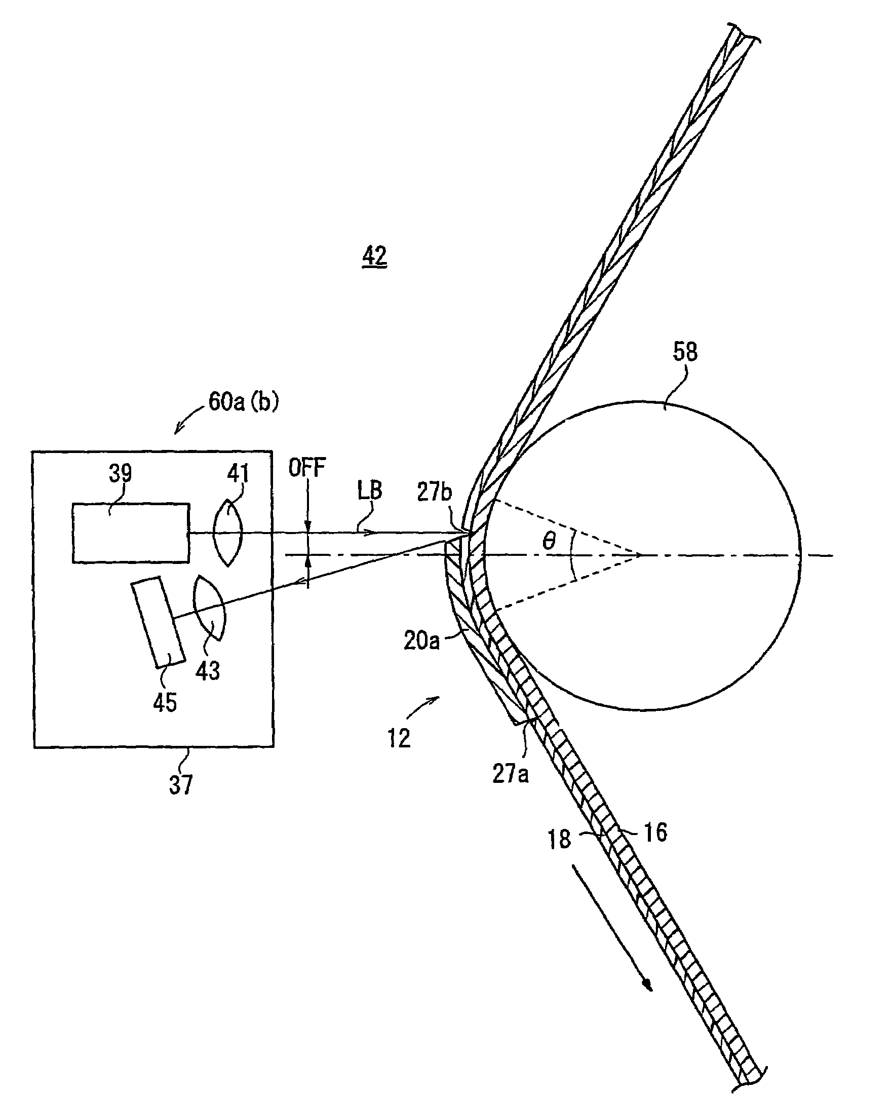
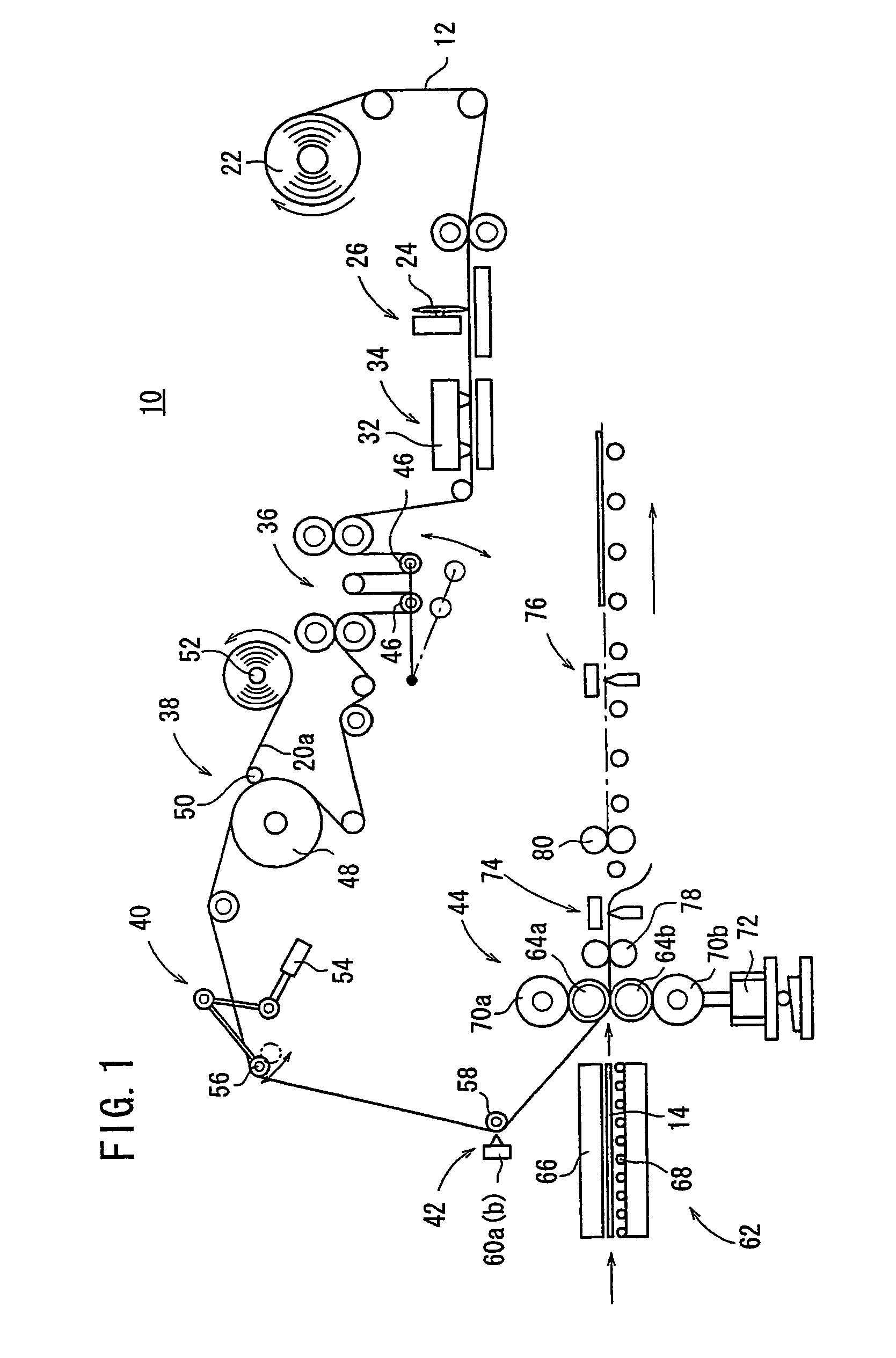
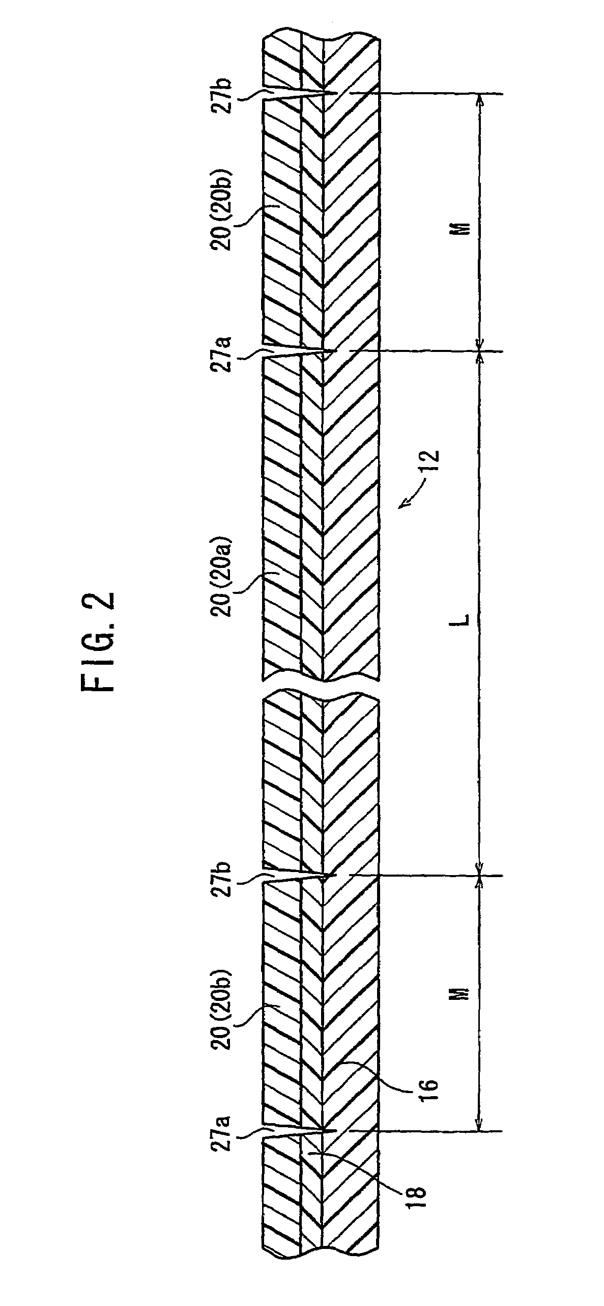
[0028]FIG. 1 schematically shows a photosensitive laminated body manufacturing apparatus 10 according to an embodiment of the present invention. As shown in FIG. 1, the photosensitive laminated body manufacturing apparatus 10 is supplied with a photosensitive sheet film 12 (sheet body) having a laminated structure shown in FIG. 2 and a plurality of glass substrates 14. As shown in FIG. 3, the photosensitive sheet film 12 and the glass substrates 14 are pressed against each other, producing color filter substrates for liquid crystal panels or organic EL panels.

[0029]The photosensitive sheet film 12 comprises a base film 16, a photosensitive resin layer 18 having a certain color such as red, green, blue, or black, for example, and a protective film 20. The base film 16, the photosensitive resin layer 18, and the protective film 20 are laminated as a sheet body. The base film 16 is made of PET (PolyEthylene Terephthalate) and has an outer surface coated with an acrylic base coat agent ...


PUM

PropertyMeasurementUnit
temperatureaaaaaaaaaa
widthaaaaaaaaaa
widthaaaaaaaaaa

Abstract

A laser beam emitted from a laser diode of each of detectors is applied to a partly cut region of a photosensitive sheet film which is spread toward the detectors by a film bending roller. Part of the laser beam which is reflected from the partly cut region is detected by an amount-of-light sensor. The laser beam that is applied to a surface of the photosensitive sheet film other than the partly cut region is reflected outside of a light-detecting area of the amount-of light sensor, and is not detected by the amount-of-light sensor.

Description

TECHNICAL FIELD[0001]The present invention relates to a detecting device for detecting a recess defined in a sheet, and a laminated body manufacturing apparatus which employs such a detecting device.BACKGROUND ART[0002]Photosensitive laminated body manufacturing apparatus are employed to manufacture a photosensitive laminated body by pressing a photosensitive pigment dispersion (photosensitive material layer) applied to a light-permeable base film (support) against a glass substrate or a resin substrate. The photosensitive laminated body is thus constructed of the glass substrate or the like with the photosensitive material layer transferred thereto. After the support is peeled off from the photosensitive laminated body, the photosensitive laminated body is exposed to a certain pattern and then developed by photolithography. The same process is performed on photosensitive films having photosensitive material layers of different colors. In this manner, color filter substrates for liq...

Claims


Application Information

Patent Timeline
Patent Type & Authority Patents(United States)
IPC IPC(8): G06M7/00G01N21/86
CPCG01N21/8916G01N21/86G01N21/892
Inventor SUEHARA, KAZUYOSHIMORI, RYOAKIYOSHI, NOBUYASU
Owner FUJIFILM CORP
Why Eureka
Try Eureka