Liquid crystal display apparatus and cooling device

a technology of liquid crystal display and cooling device, which is applied in the direction of instruments, color television details, projectors, etc., can solve the problems of obvious noise image quality may sometimes deteriorate, and the sound generated by the cooling fan becomes noise, so as to improve the reliability of the apparatus, suppress the noise, and improve the cooling efficiency

Inactive Publication Date: 2009-05-19
SONY CORP
View PDF10 Cites 63 Cited by
  • Summary
  • Abstract
  • Description
  • Claims
  • Application Information

AI Technical Summary

Benefits of technology

[0013]In the air cooling system, a cooled air is supplied to a display area of the liquid crystal panel by a cooling fan to thereby cool the liquid crystal panel. Therefore, this system suffers from disadvantages that sounds generated by driving the cooling fan become noise. In the case of the projection type liquid crystal display apparatus, the liquid crystal panel is small-sized in order to satisfy a demand for a small-sized device, as a result, a heating amount per a unit area increases. Therefore, the cooling fan must be made large to improve a cooling effect, which results the disadvantage of the obvious noise generated by the cooling fan. In this method, by sending the cooling air from the cooling fan, dust included in the cooling air may be frequently deposited on a surface of the liquid crystal panel, so the image quality may sometimes deteriorate due to the dust. Also, in this method, when fixing a polarizing plate, a sappier glass substrate having a high thermal conductivity may be used to thereby radiate (dissipate) heat efficiently, so it suffers from a disadvantage that a production cost increases.
[0014]On the other hand, in the fluid cooling system, a pump is used to supply a cooling fluid to the display area of the liquid crystal panel to thereby cool the liquid crystal panel. In this system, the light passed through the liquid crystal panel and the cooling fluid is displayed as an image. In this system, since the cooling fluid is used, the liquid crystal panel can be cooled at higher cooling efficiency than that of the cooling air and the noise caused by the drive sound can be suppressed. Along with this, the sappier glass substrate is unnecessary when fixing the polarizing plate, so a low-priced glass substrate can be used and the production cost can be reduced.
[0017]Therefore, in the case where the liquid crystal panel of the liquid crystal display apparatus is cooled and adjusted to the rated temperature range, since the cooling efficiency is insufficient, it may be difficult to improve a reliability of the apparatus. Also, it may be difficult to suppress the noise and reduce the production cost and improve the image quality.
[0018]It is desirable to provide a liquid crystal apparatus capable of improving the cooling efficiency for improving the reliability of the apparatus, and suppressing the noise and reducing the production cost, and improving the image quality, and a cooling device for the same.
[0025]According to the embodiments of the present invention, the liquid crystal apparatus capable of improving the cooling efficiency to improve the reliability of the apparatus, and suppressing the noise and reducing the production cost, and improving the image quality, and a cooling device for the liquid crystal display apparatus can be provided.

Problems solved by technology

Therefore, this system suffers from disadvantages that sounds generated by driving the cooling fan become noise.
Therefore, the cooling fan must be made large to improve a cooling effect, which results the disadvantage of the obvious noise generated by the cooling fan.
In this method, by sending the cooling air from the cooling fan, dust included in the cooling air may be frequently deposited on a surface of the liquid crystal panel, so the image quality may sometimes deteriorate due to the dust.
Also, in this method, when fixing a polarizing plate, a sappier glass substrate having a high thermal conductivity may be used to thereby radiate (dissipate) heat efficiently, so it suffers from a disadvantage that a production cost increases.
Specifically, although the high cooling efficiency is demanded for the projection type liquid crystal display apparatus as described above, so the cooling efficiency may sometimes be low and insufficiency in the fluid cooling method.
Further, in the fluid cooling system, an air bubble appears in the cooling fluid due to a circulation thereof, which may cause the image quality deteriorate.
For example, the air bubble of a diameter in 100 to 300 μm per a pixel in 10 μm width, may appear in the cooling fluid, as a result, since light transmittance of the air bubble is different from that of the cooling fluid, the light intensity passed through the air bubble is different from that of the cooling fluid, which may result the disadvantage of the obvious deteriorate of the image quality.

Method used


Image

  • Liquid crystal display apparatus and cooling device
  • Liquid crystal display apparatus and cooling device
  • Liquid crystal display apparatus and cooling device

Examples


first embodiment

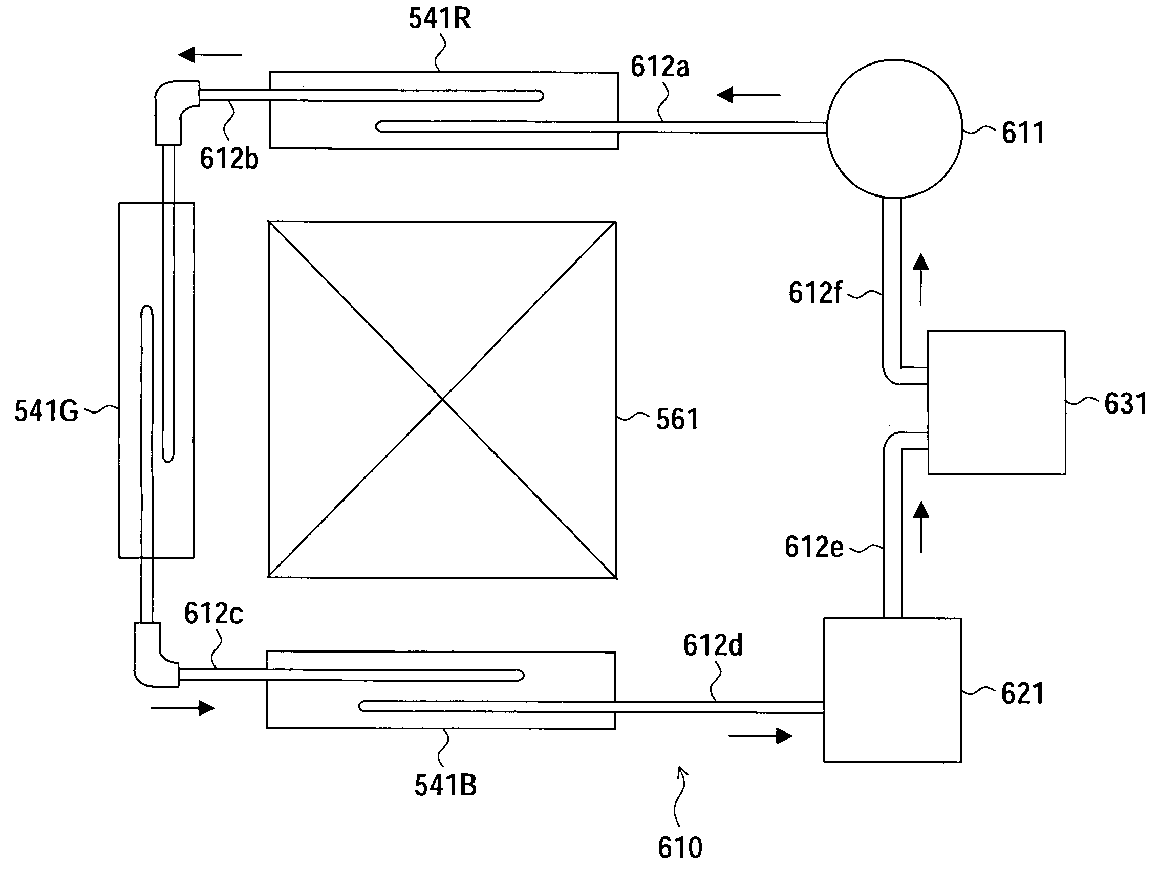
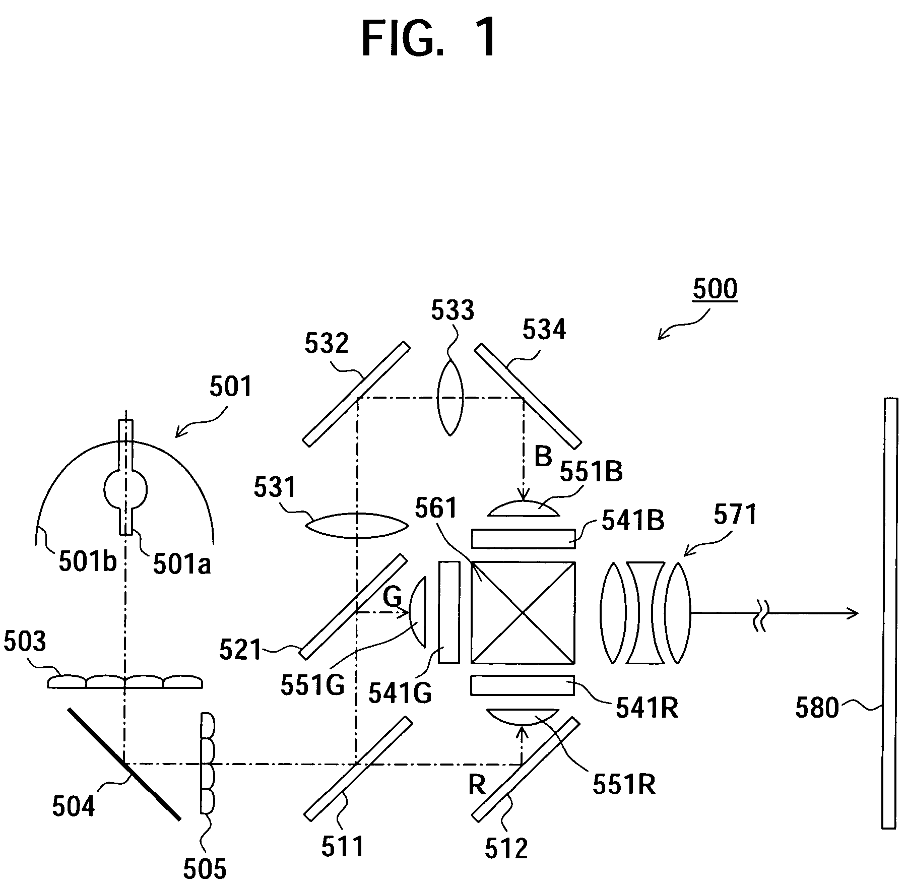
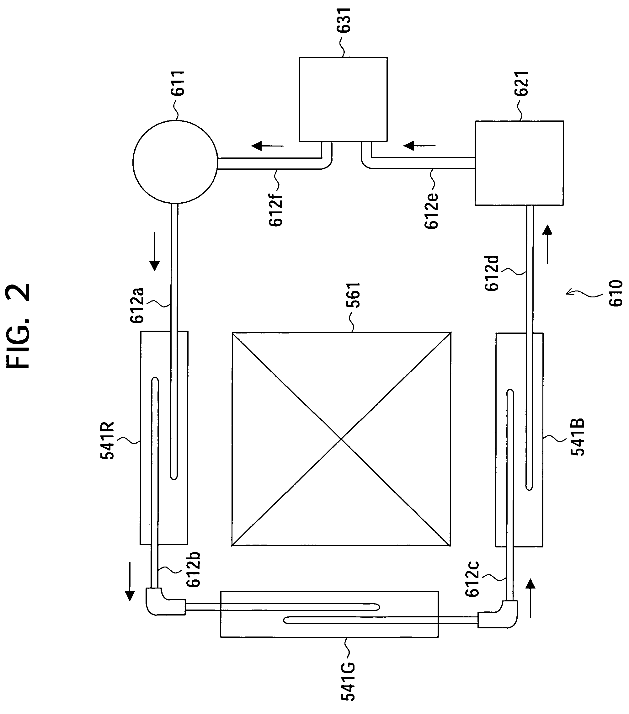
[0035]FIG. 1 is a configuration view of a liquid crystal display apparatus according to a first embodiment of the present invention.

[0036]As shown in FIG. 1, a liquid crystal display device 500 according to the present embodiment is a three-plate projection type display device, and has a light source 501, a first lens array 503, a first reflection mirror 504, a second lens array 505, a first dichroic mirror 511, a second reflection mirror 512, a second dichroic mirror 521, a first relay lens 531, a third reflection mirror 532, a second relay lens 533, a fourth reflection mirror 534, a first liquid crystal display unit 541R, a second liquid crystal display unit 541G, a third liquid crystal display unit 541B, a first condenser lens 551R, a second condenser lens 551G, a third condenser lens 551B, a dichroic prism 561, and a projection lens unit 571.

[0037]The above respective units of the liquid crystal display device 500 according to the present embodiment will be described successivel...

second embodiment

[0119]FIGS. 6A and 6B are views showing the first liquid crystal display unit 541R of the liquid crystal display device according to the present embodiment, in which FIG. 6A is a cross-sectional view of the first liquid crystal display unit 541R and FIG. 6B is a plan view seem from the first cooling fluid receiving unit 711a side in the first liquid crystal display unit 541R. Note that, the second liquid crystal display unit 541G and the third liquid crystal display unit 541B are formed in the same way as the first liquid crystal display unit 541R as shown in FIGS. 6A and 6B.

[0120]As shown in FIGS. 6A and 6B, the liquid crystal display device 500 according to the present embodiment is the same configuration as the first embodiment except that a first and a second polarizing plate protection units 725a and 725b are included and shapes of the first and the second flow path block units 751a and 751b are different. Therefore, components the same as those of the first embodiment are assi...


PUM

PropertyMeasurementUnit
surface roughnessaaaaaaaaaa
diameteraaaaaaaaaa

Abstract

A liquid crystal display device constrains the injection of air bubbles in a cooling fluid into a display panel. In the display device, the cooling fluid is supplied to a receiving space of a receiving unit placed and opposed to a surface of a liquid crystal panel to which the light is emitted from a light source to thereby cool the liquid crystal panel. Namely, by a cooling fluid pump, the cooling fluid received in the receiving unit is drained from a drain port and the cooling fluid is supplied from a feed port to the receiving unit and received in the receiving space. In the above case, a part of a flow path of the cooling fluid supplied from the feed port is blocked by a flow path block unit placed and opposed to the feed port to thereby disperse the flow thereof around the flow path block unit.

Description

CROSS REFERENCES TO RELATED APPLICATIONS[0001]The present invention contains subject matter related to Japanese Patent Application JP 2004-363056 filed in the Japanese Patent Office on Dec. 15, 2004, the entire contents of which being incorporated herein by reference.BACKGROUND OF THE INVENTION[0002]1. Field of the Invention[0003]The present invention relates to a liquid crystal display apparatus and a cooling device, particularly, a liquid crystal display apparatus cooling a surface of a liquid crystal panel to which light is emitted from a light source and transmitting the light from the light source via a cooling fluid, and a cooling device for the same.[0004]2. Description of the Related Art[0005]There is known a liquid crystal display apparatus including a liquid crystal panel in which a liquid crystal layer is sealed between a pair of substrates. In the liquid crystal apparatus, the liquid crystal panel modulates the light emitted from a light source. And the apparatus display...

Claims


Application Information

Patent Timeline
Patent Type & Authority Patents(United States)
IPC IPC(8): G02F1/1333
CPCG02F1/133385G03B21/16H04N9/3144H04N9/3197
Inventor DEWA, SHIGEKUNIYAMADA, MASASHIOHKUBO, TAKUJINASU, TAKASHI
Owner SONY CORP
Why Eureka
Try Eureka