Thermal lance assembly

a technology of lance and assembly, which is applied in the direction of manufacturing converters, charge manipulation, furnaces, etc., can solve the problems of affecting the service life of the telescoping tube, so as to achieve the effect of improving the service life, enhancing the burn characteristics, and consuming more quickly

Active Publication Date: 2009-05-26
HARASYM MICHAEL F
View PDF6 Cites 4 Cited by
  • Summary
  • Abstract
  • Description
  • Claims
  • Application Information

AI Technical Summary

Benefits of technology

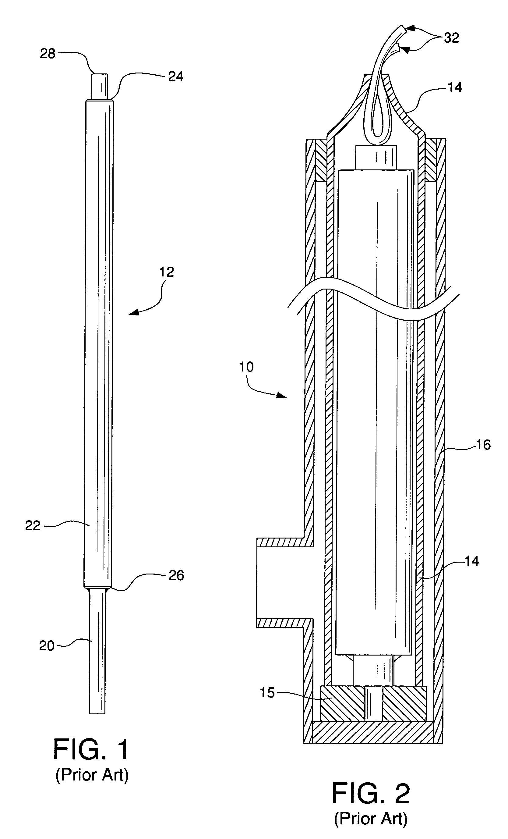
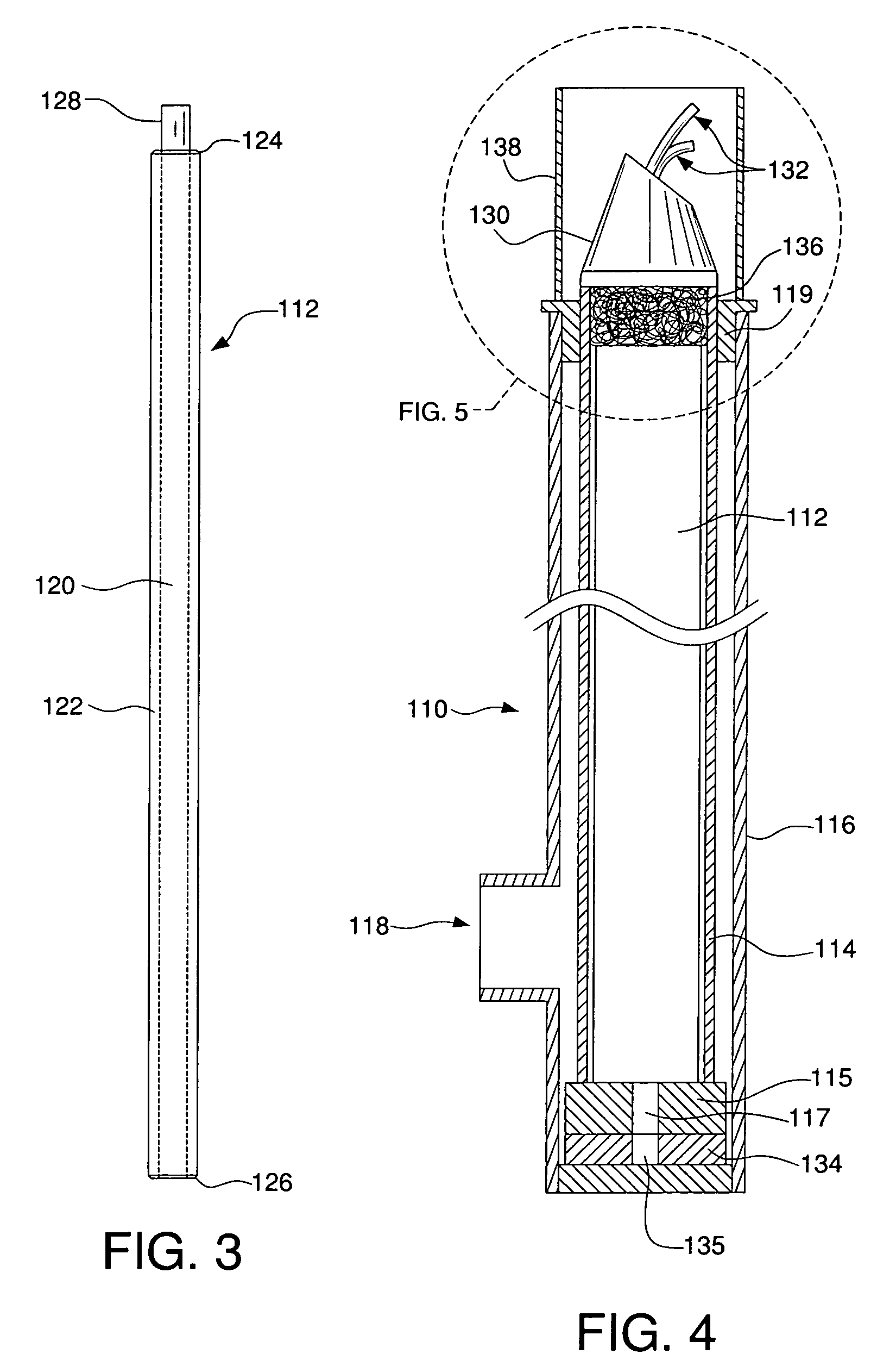
[0011]The present improvement provides a roll-formed rod and low carbon sheath combination lance with enhanced burn characteristics. The fixed attachment of the rod 20 to the sheath 22 in the prior art lance requires that they advance together and be consumed at the same rate. The present improvement allows the roll-formed rod to advance within the sheath and thus be consumed more rapidly than the sheath, with the advantage of providing a more reliable burn. A main cause of an unsuccessful unplug attempt with a thermal lance is that too much of the telescoping tube can be consumed, and thereby disrupt the directed oxygen path, before the combustible lance burns through the obstruction and initiates metal flow. Thus, increasing the burn rate at the tip of the lance promotes a deeper burn in the same time interval and lessens the risk of oxygen disruption. Also, the rod and sheath will be consumed simultaneously, but at different rates. For example, a rod whose starting length was ½ inch longer than the sheath was then measured at 2 inches shorter than the sheath following penetration of a test sample. To penetrate the test sample, 15 inches of rod were consumed, as compared to 12.5 inches of sheath consumed. Also, even if the rod is completely consumed, the sheath will continue to burn and penetrate. This results in an estimated 25 to 30% improvement in performance.
[0012]The invention also provides a telescoping thermal lance apparatus for unplugging a molten metal vessel's discharge port. The apparatus includes an elongated tubular housing having a hollow interior chamber and a conduit for introducing pressurized oxygen into the housing, and has an improved axially displaceable thermal lance disposed within the housing and adapted to be projected upwardly when pressurized oxygen is introduced into the housing. The improved lance includes a low carbon steel sheath having an internal bore into which is disposed a thin cylindrical rod that is roll-formed from low carbon steel sheet. The rod is sized for conforming fit in the bore of the sheath and is longer than the length of the sheath. The rod is inserted into the bore of the sheath and allowed to move axially within the sheath under propulsion of the pressurized oxygen to allow the rod to burn at a rate that is independent of the burn rate of the sheath.

Problems solved by technology

A main cause of an unsuccessful unplug attempt with a thermal lance is that too much of the telescoping tube can be consumed, and thereby disrupt the directed oxygen path, before the combustible lance burns through the obstruction and initiates metal flow.
Also, even if the rod is completely consumed, the sheath will continue to burn and penetrate.

Method used


Image

  • Thermal lance assembly
  • Thermal lance assembly
  • Thermal lance assembly

Examples


Embodiment Construction

[0019]The invention is an improved thermal lance and lance apparatus for unplugging a vessel discharge port, for example, in a refractory lined ladle, tundish, or furnace used in the casting or melting of molten steel. As shown in FIG. 4, a lance apparatus 110 includes a tubular lance housing 116 having an axially displaceable tube 114 disposed within the interior of the housing. The tube 114 is preferably made of stainless or other high carbon steel. The tube 114 may have a flared base or a base flange 115 to keep it centered in the housing, and the housing includes a bushing 119 near the top end to prevent the tube from completely exiting the housing. The bottom of the tube 116 has an aperture 117 to allow oxygen to flow into the tube.

[0020]Disposed within the tube 114 is a thermal lance 112. A conduit 118 communicates pressurized oxygen to the interior of the tube housing 116. When the apparatus is placed in line with an obstructed discharge port and an oxygen supply is opened, t...


PUM

PropertyMeasurementUnit
pressureaaaaaaaaaa
lengthaaaaaaaaaa
lengthaaaaaaaaaa

Abstract

An improved thermal lance is made of a low carbon steel sheath having an internal bore and a thin cylindrical rod that is roll-formed from low carbon steel sheet. The rod being sized for conforming fit in the bore of the sheath and has a length dimension that is longer than the length of the sheath. The rod is inserted into the bore of the sheath and allowed to move axially within the sheath under propulsion of the pressurized oxygen to allow the rod to be burned at a rate independent of the burn rate of the sheath. A thermal lance assembly using the improved lance also includes a magnet located near the bottom of the lance housing to keep the lance from moving during routine handling and storage.

Description

BACKGROUND OF THE INVENTION[0001]1. Field of the Invention[0002]This invention is related to the general field and classification of molten metal dispensing, and to the more specific field of apparatus for unplugging a vessel discharge port with a telescoping thermal lance.[0003]2. Description of Related Art[0004]The use of a telescoping thermal lance to burn through an obstructing plug in the discharge port of a vessel containing molten metal is described in U.S. Pat. No. 4,450,986 to Harasym and Lanza; U.S. Pat. No. 4,746,037 to Harasym; and U.S. Pat. No. 4,877,161 to Harasym. Reference can be made to those publications, if needed, for background on the configuration and operation of such discharge ports, the causes of their blockage, and the general use of telescoping thermal lances to burn through the obstruction and initiate flow of the molten metal through the discharge port.[0005]In U.S. Pat. No. 4,450,986, the telescoping lance assembly (identified by reference number 41 on ...

Claims


Application Information

Patent Timeline
Patent Type & Authority Patents(United States)
IPC IPC(8): B23K7/00
CPCC21B7/12C21C5/4653F27D3/1527
Inventor HARASYM, MICHAEL F.
Owner HARASYM MICHAEL F
Why Eureka
Try Eureka