Lighting device image, reading apparatus, and image forming apparatus

a technology of reading apparatus and light source, which is applied in the direction of lighting support devices, lighting and heating apparatus, instruments, etc., can solve the problems of insufficient quantity of light, uneven image concentration due to illuminance ripple, and inability to read performan

Active Publication Date: 2009-05-26
RICOH KK
View PDF26 Cites 53 Cited by
  • Summary
  • Abstract
  • Description
  • Claims
  • Application Information

AI Technical Summary

Benefits of technology

[0085]Consequently, when a ray emitted from the LED 32 and condensed by the condensing body 33 is irradiated on the surface of the document, as the condensing body 33 is closer to the reading light reflection area B, even if the document on the contact glass 12 gets lifted, a quantity of light rays irradiated on the surface of the document above the reading optical axis A can be secured more, lighting performance of the lighting apparatus 18 is maintained better, and reading performance of the image reading apparatus 13 is maintained better.
[0097]Rays irradiated on the surface of the document on the contact glass 12 are divided into rays, which pass through the direct emitting portion 52 of the condensing body 33 and are directly irradiated, and rays, which are emitted from the indirect emitting portion 53 of the condensing body 33 and irradiated via the reflection mechanism 42. These two kinds of rays are irradiated toward the surface of the document above the reading optical axis A from both sides in the sub-scanning direction at the time of image reading across the reading optical axis A. Therefore, the position of a peak value of a quantity of light of rays irradiated on the surface of the document can be brought closer to the reading optical axis A.
[0046]FIG. 20 is a front view of a lighting device according to a twelfth embodiment of the present invention
[0097]Rays irradiated on the surface of the document on the contact glass 12 are divided into rays, which pass through the direct emitting portion 52 of the condensing body 33 and are directly irradiated, and rays, which are emitted from the indirect emitting portion 53 of the condensing body 33 and irradiated via the reflection mechanism 42. These two kinds of rays are irradiated toward the surface of the document above the reading optical axis A from both sides in the sub-scanning direction at the time of image reading across the reading optical axis A. Therefore, the position of a peak value of a quantity of light of rays irradiated on the surface of the document can be brought closer to the reading optical axis A.
[0050]FIG. 24 is a disassembled perspective view of a lighting device according to a fourteenth embodiment of the present invention;
[0105]The reflection plate 73 has a function of condensing rays, which have passed through the light guide member 38, toward the surface of the document on the contact glass 12 above the reading optical axis A and a function of reflecting a part of the rays, which have passed through the light guide member 38, to the second reflection plate 44. The reflection plate 73 and the second reflection plate 44 constitute the reflection mechanism 42 that reflects a part of the rays, which have emitted from the condensing body 72, from the opposite side across the reading optical axis A.
[0072]In such a structure, angles of all rays, which have been emitted from the LED 32 and have passed through the condensing body 33, are maintained to be smaller than the critical angle “θ” of the contact glass 12. Thus, the rays are transmitted through the contact glass 12 without being reflected by the contact glass 12 and are irradiated on the surface of the document. Consequently, all the rays emitted from the LEDs 32 can be utilized effectively to light the surface of the document. Therefore, even in the case in which the LEDs 32, which are point light sources with a small quantity of light, are used as light sources for the lighting device 18, a quantity of light necessary for image reading can be secured.
[0085]Consequently, when a ray emitted from the LED 32 and condensed by the condensing body 33 is irradiated on the surface of the document, as the condensing body 33 is closer to the reading light reflection area B, even if the document on the contact glass 12 gets lifted, a quantity of light rays irradiated on the surface of the document above the reading optical axis A can be secured more, lighting performance of the lighting apparatus 18 is maintained better, and reading performance of the image reading apparatus 13 is maintained better.
[0085]Consequently, when a ray emitted from the LED 32 and condensed by the condensing body 33 is irradiated on the surface of the document, as the condensing body 33 is closer to the reading light reflection area B, even if the document on the contact glass 12 gets lifted, a quantity of light rays irradiated on the surface of the document above the reading optical axis A can be secured more, lighting performance of the lighting apparatus 18 is maintained better, and reading performance of the image reading apparatus 13 is maintained better.
[0054]FIG. 28 is a side view explaining a state in which rays emitted from LEDs and transmitted through a condensing body are diffused at random in a light diffusing portion;
[0072]In such a structure, angles of all rays, which have been emitted from the LED 32 and have passed through the condensing body 33, are maintained to be smaller than the critical angle “θ” of the contact glass 12. Thus, the rays are transmitted through the contact glass 12 without being reflected by the contact glass 12 and are irradiated on the surface of the document. Consequently, all the rays emitted from the LEDs 32 can be utilized effectively to light the surface of the document. Therefore, even in the case in which the LEDs 32, which are point light sources with a small quantity of light, are used as light sources for the lighting device 18, a quantity of light necessary for image reading can be secured.
[0080]As another one of the contrivances for providing the condensing body 33 close to the reading light reflection area B, the LEDs 32 are formed in an elongated shape toward a direction along the main scanning direction at the time of image reading. In other words, the LEDs 32 are designed to have a shape in which a width dimension L in the sub-scanning direction when reading the document is reduced. This makes it possible to provide a central position of the LEDs 32 attached to the substrate 36a closer to the width direction of the substrate 36a, and the condensing body 33 can be provided closer to the reading light reflection area B.
[0076]Therefore, when the surface of the document is lighted using this condensing body 33a, rays condensed by the condensing body 33a are transmitted through and irradiated on the surface of the document without being reflected on the contact glass 12. Thus, all rays emitted from the LEDs 32 can be utilized effectively to light the surface of the document.
[0067]The condensing body 33 includes a lens 37, a light guide member 38, and a condensing lens 39, which are integrally molded, and is formed in an elongated shape having substantially the same length as the substrate 36. The condensing body 33 is positioned in such a manner that its length is aligned with the main scanning direction of reading the document.
[0067]The condensing body 33 includes a lens 37, a light guide member 38, and a condensing lens 39, which are integrally molded, and is formed in an elongated shape having substantially the same length as the substrate 36. The condensing body 33 is positioned in such a manner that its length is aligned with the main scanning direction of reading the document.
[0067]The condensing body 33 includes a lens 37, a light guide member 38, and a condensing lens 39, which are integrally molded, and is formed in an elongated shape having substantially the same length as the substrate 36. The condensing body 33 is positioned in such a manner that its length is aligned with the main scanning direction of reading the document.
[0067]The condensing body 33 includes a lens 37, a light guide member 38, and a condensing lens 39, which are integrally molded, and is formed in an elongated shape having substantially the same length as the substrate 36. The condensing body 33 is positioned in such a manner that its length is aligned with the main scanning direction of reading the document.
[0096]The indirect emitting portion 53 is formed by cutting a part of the condensing lens 39 and a part of the light guide member 38 and is also cut in a direction in which rays emitted from the indirect emitting portion 53 travel toward the first reflection plate 43.
[0096]The indirect emitting portion 53 is formed by cutting a part of the condensing lens 39 and a part of the light guide member 38 and is also cut in a direction in which rays emitted from the indirect emitting portion 53 travel toward the first reflection plate 43.

Problems solved by technology

Therefore, an amount of generation of flare light is different when the surface of the document is whitish and blackish, and decline in reading performance due to an influence of the flare light is caused.
As a result, when an image is formed according to read image data, unevenness in image concentration due to the illuminance ripple occurs.
However, since the point light sources have a small quantity of light, insufficiency of a quantity of light tends to occur unless a direction of irradiation of light is considered sufficiently.
Therefore, when the surface of the document lifts from a contact glass, a rate of decline in a quantity of light irradiated on the surface of the document is large even if a dimension of the lift is small, and reading performance tends to fall.

Method used


Image

  • Lighting device image, reading apparatus, and image forming apparatus
  • Lighting device image, reading apparatus, and image forming apparatus
  • Lighting device image, reading apparatus, and image forming apparatus

Examples


first embodiment

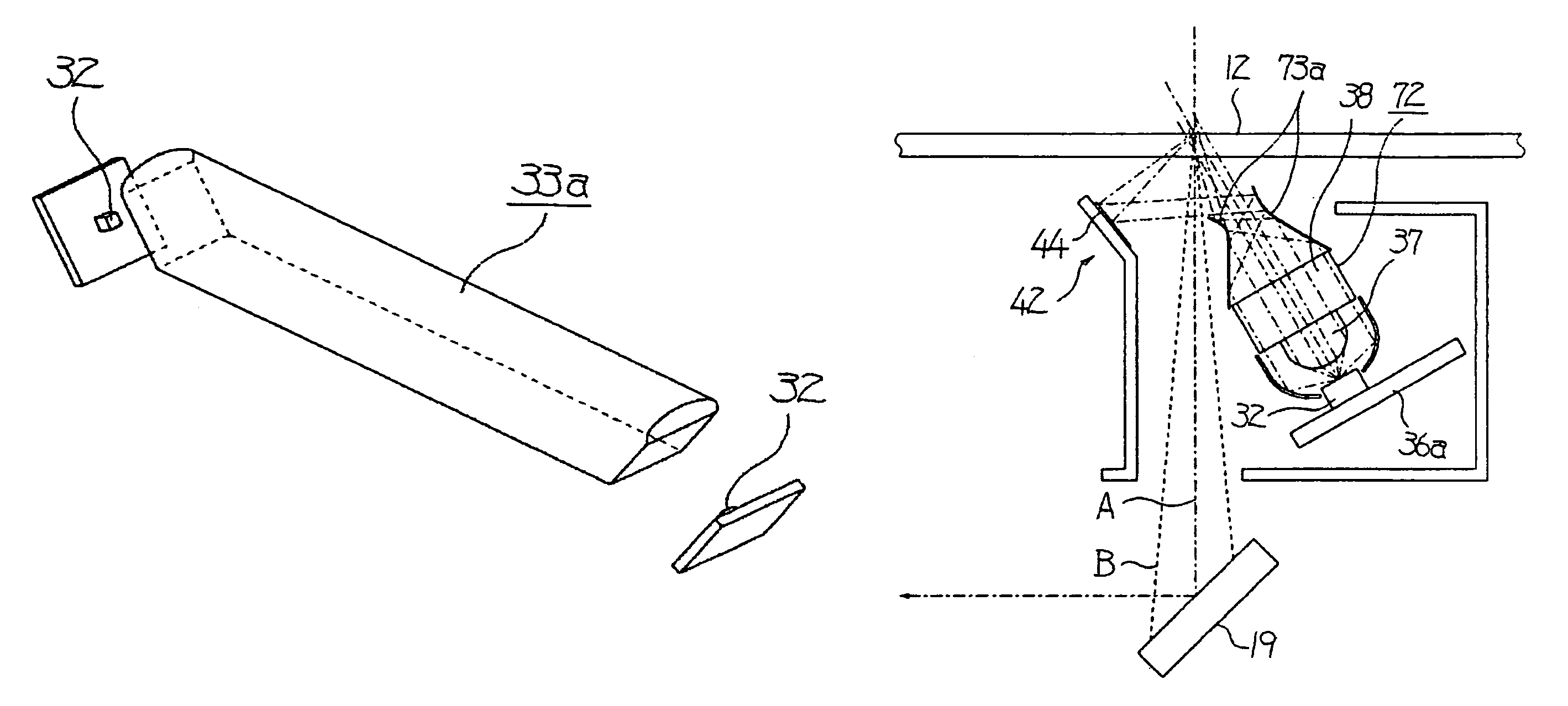
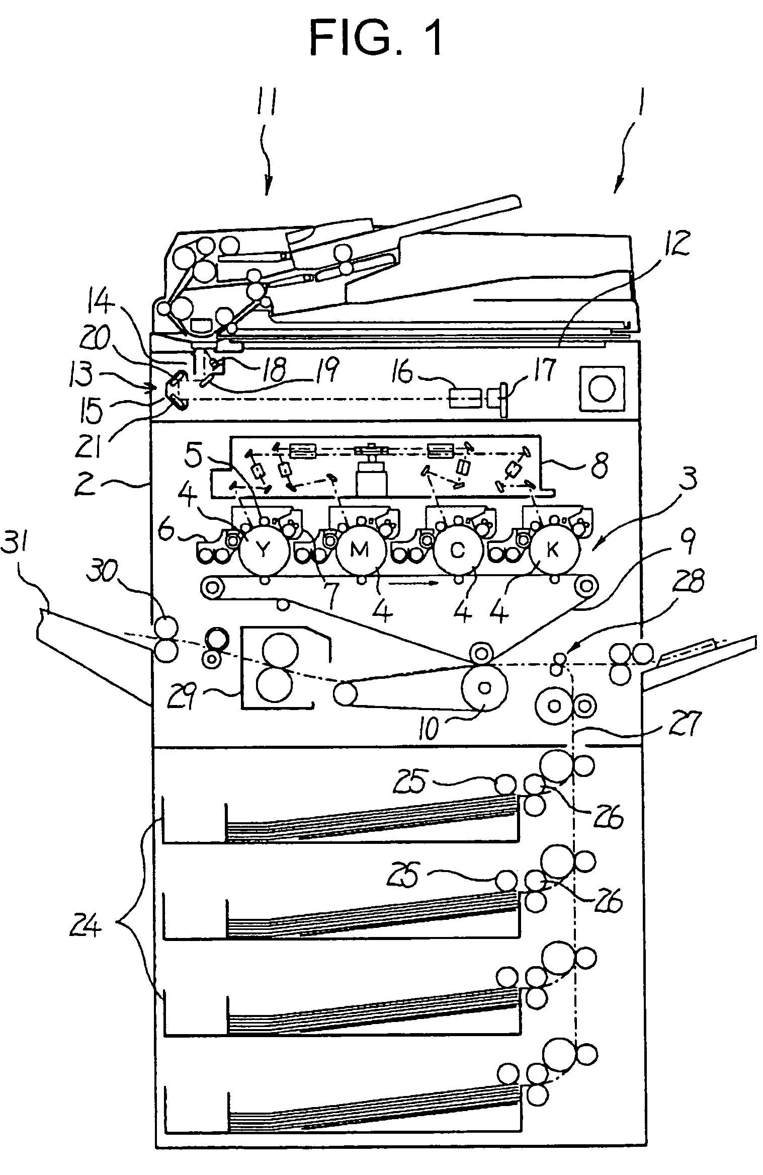
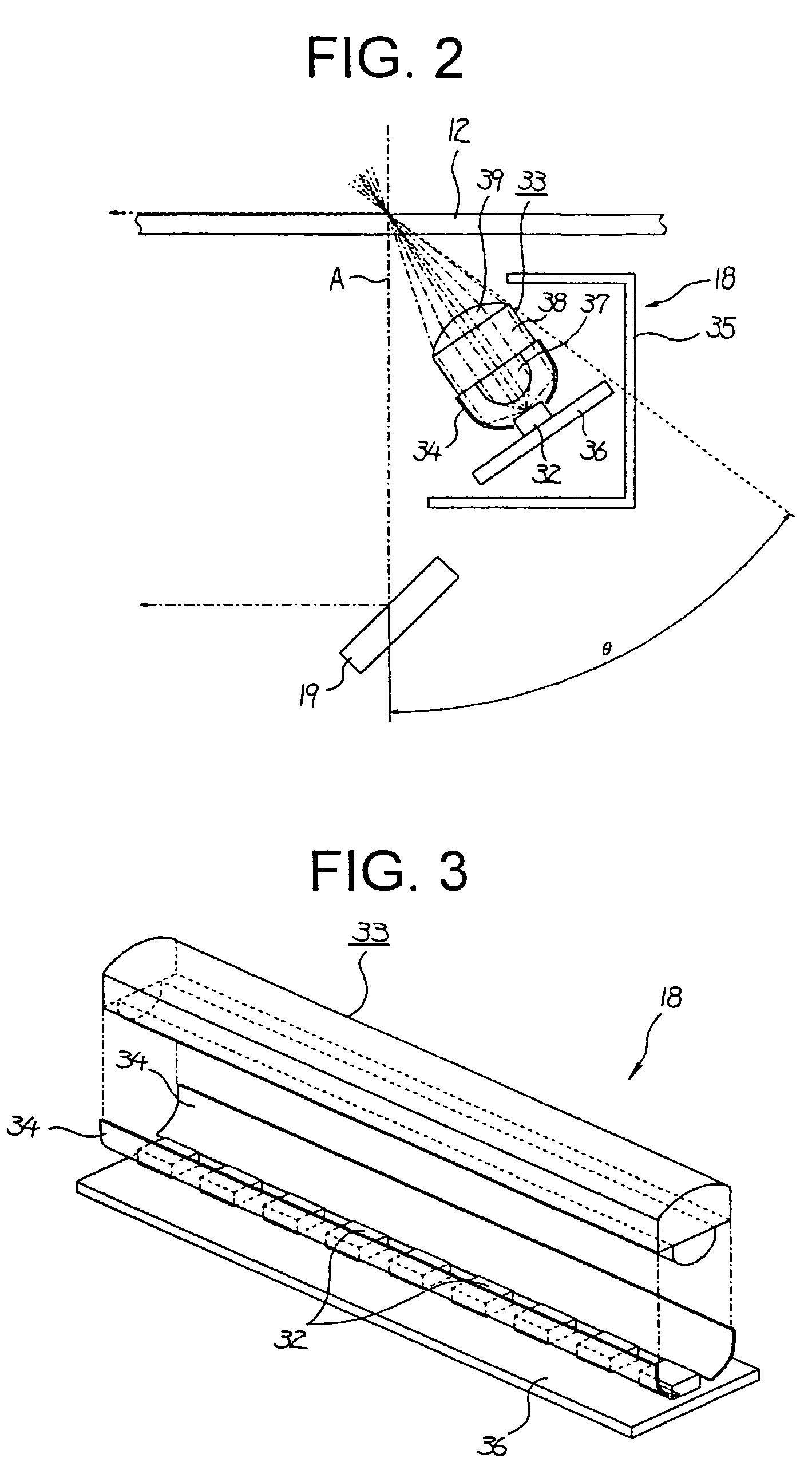
[0058]the present invention will be explained with reference to FIGS. 1 to 4. FIG. 1 is a schematic front view of an internal structure of a full-color copying machine 1 that is an image forming apparatus to which the present invention is applied.

[0059]An image forming unit 3 for forming a color image is provided in a central part in an apparatus body 2 of the copying machine 1. This image forming unit 3 includes: four drum-like photosensitive members 4 that are arranged in parallel horizontally to be spaced apart at an equal interval; charging rollers 5 that are arranged in outer peripheries of the respective photosensitive members 4 and form toner images on outer peripheral surfaces of the photosensitive members 4 with an electrophotographic process; developing devices 6; cleaning devices 7; an exposing device 8 that exposes the uniformly charged outer peripheral surfaces of the photosensitive members 4 to a laser beam according to image data to thereby form electrostatic latent i...

eighth embodiment

[0108]the present invention will be explained with reference to FIGS. 14 and 15. A lighting device 75 in the eighth embodiment includes the plural LEDs 32 serving as point light sources, a condensing body 76, and a reflection mechanism 77.

[0109]The condensing body 76 is arranged in front in an emitting direction of rays emitted from the LEDs 32 and condenses the rays emitted from the LEDs 32 within a reading width in the sub-scanning direction when reading a document (within a width appropriate for a reading line width in the sub-scanning direction). In addition, in this condensing body 76, an incident side protrusion 78, in which diffused rays emitted from the LEDs 32 are made incident to be converted into parallel rays, a direct emitting portion 79, which directly emits the incident rays to a surface of a document, and a prism reflection surface portion 80, which reflects the incident rays to the reflection mechanism 77, are formed.

[0110]The reflection mechanism 77 is a tabular re...

tenth embodiment

[0122]the present invention will be explained with reference to FIG. 18. A lighting device 85 of the tenth embodiment includes the plural LEDs 32 serving as point light sources, a condensing body 86, and the reflection mechanism 77.

[0123]The condensing body 86 is arranged in front in an emitting direction of rays emitted from the LEDs 32 and condenses the rays emitted from the LEDs 32 within a reading width in the sub-scanning direction when reading a document (within a width appropriate for a reading line width in the sub-scanning direction). In addition, in this condensing body 86, the incident side protrusion 78, in which diffused rays emitted from the LEDs 32 are made incident to be converted into parallel rays, a prism reflection surface portion 87, which reflects the incident rays toward a surface of a document, and an indirect emitting portion 88, which causes the incident rays travel toward the reflection mechanism 77, are formed.

[0124]The reflection mechanism 77 is a tabula...


PUM


Abstract

A lighting device used in an image forming apparatus includes point light sources that emits rays; and a condensing body that is arranged in a direction of the rays emitted from the point light source and that condenses the rays on a surface of a document, which is placed on a contact glass, within a reading width in a sub-scanning direction of the document. The condensing body is arranged in a direction in which angles of all rays, which pass through the condensing body, are smaller than a critical angle of total reflection on the contact glass.

Description

CROSS-REFERENCE TO RELATED APPLICATIONS[0001]The present document incorporates by reference the entire contents of Japanese priority documents, 2003-295160 filed in Japan on Aug. 19, 2003, 2003-390764 filed in Japan on Nov. 20, 2003, and 2004-006448 filed in Japan on Jan. 14, 2004.BACKGROUND OF THE INVENTION[0002]1) Field of the Invention[0003]The present invention relates to a lighting device, an image reading apparatus, and an image forming apparatus.[0004]2) Description of the Related Art[0005]An image reading apparatus, such as a scanner, has a light source. This light source is located above a contact glass and emits rays toward a surface of a document to be scanned. The light reflected from the surface of the document is focuses on a photoelectric conversion element (CCD) via a lens.[0006]As a light source for such an image reading apparatus, a bar light source like a fluorescent tube or a xenon lamp or a point light source such as an LED is used.[0007]When the bar light sourc...

Claims


Application Information

Patent Timeline
Patent Type & Authority Patents(United States)
IPC IPC(8): H04N1/04F21V7/04G02B6/32H04N1/028
CPCH04N1/02815H04N1/02835H04N1/02865H04N1/0289
Inventor SAKURAI, YASUOKOHCHI, MASASHI
Owner RICOH KK
Why Eureka
Try Eureka