
In-series two chain continuously variable transmission

a continuously variable transmission and chain technology, applied in the direction of gearing, cycle equipment, hoisting equipment, etc., can solve the problems of limited number of vehicles featuring such transmissions, limited application of belt/chain drive in larger passenger vehicles and medium-sized trucks, and inability to use single belt cvt technology, etc., to achieve adequate on-road speed, improve fuel economy, and increase the size and weight of the cvt

Inactive Publication Date: 2009-06-02
BROWN ALBERT W
View PDF86 Cites 12 Cited by
  • Summary
  • Abstract
  • Description
  • Claims
  • Application Information

AI Technical Summary

Benefits of technology

This configuration allows for a larger ratio spread with smaller pulleys, reducing the size and weight of the transmission and lowering manufacturing and assembly costs, while maintaining compactness and ease of installation.

Problems solved by technology

While CVT vehicles offer an upside of improved fuel economy, several perceived drawbacks have greatly limited the number of vehicles featuring such transmissions.
In particular, belt / chain drives have found limited application in larger passenger vehicles and medium size trucks.
These types of vehicles commonly require drive ratios that make single belt CVT technology not feasible.
While large ranges can be created with large pulleys, such an approach increases the size and weight of the CVT.
Another difficulty that is associated with prior continuously variable transmission designs in general is the large number of parts and the complicated assembly resulting from the large number of parts.
Both the number of parts and the specialized nature of the parts drive up the manufacturing cost of the transmissions.
Moreover, the complicated assembly increases required assembly man hours, which further increases the cost of the transmissions.

Method used


Image

  • In-series two chain continuously variable transmission
  • In-series two chain continuously variable transmission
  • In-series two chain continuously variable transmission

Examples


Embodiment Construction

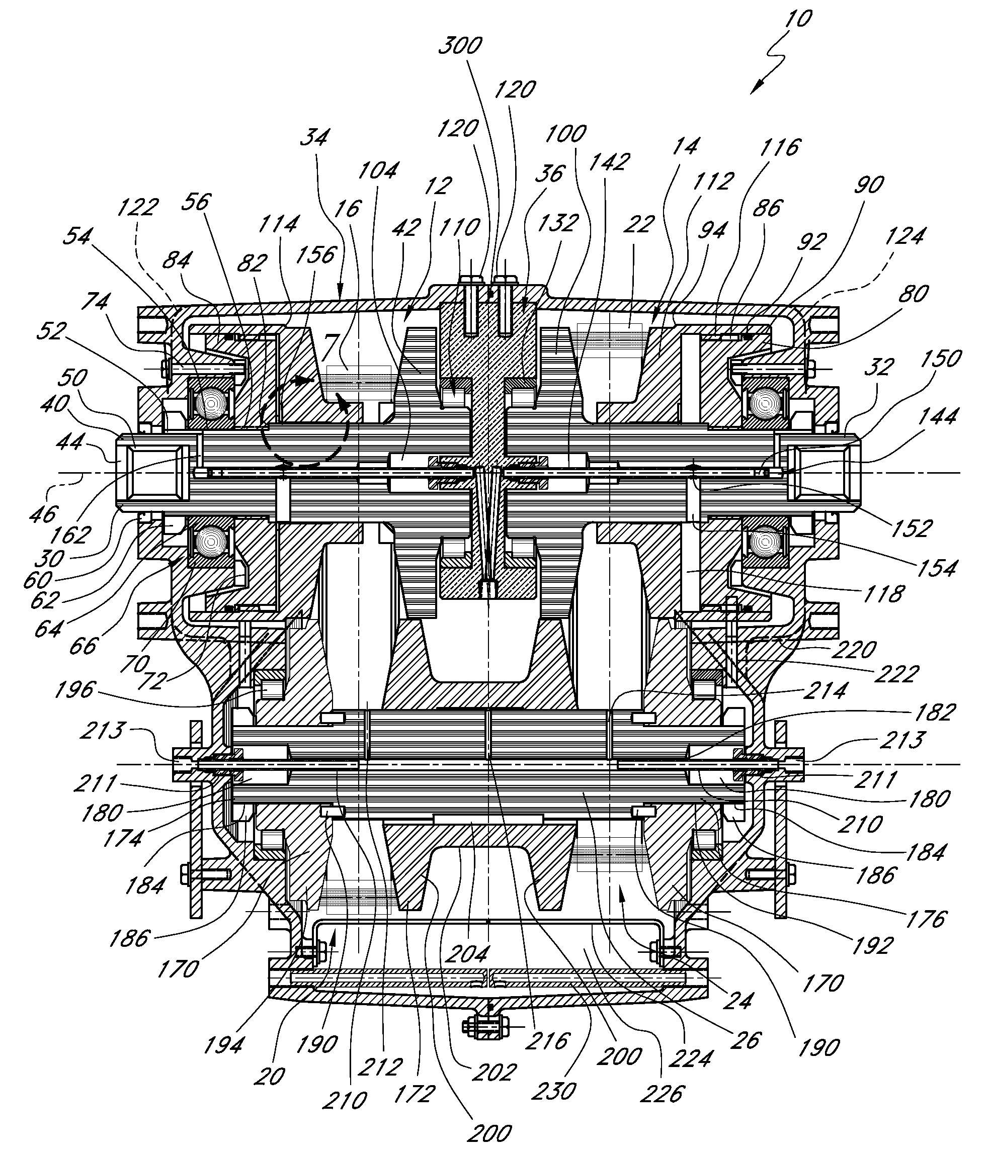
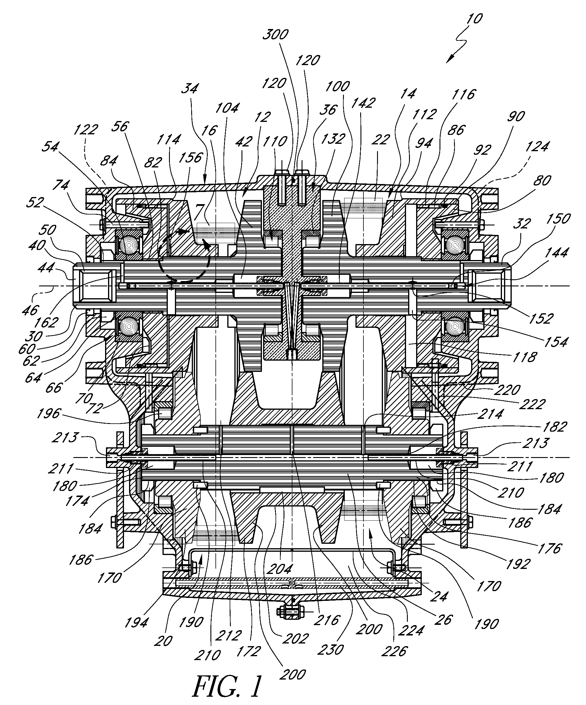
[0017]FIG. 1 illustrates an embodiment of a transmission 10 that is arranged and configured in accordance with certain features, aspects and advantages of the present invention. While shown in the context of a dual belt transmission, some of the features, aspects and advantages can be used in single belt transmission, such as that shown in copending U.S. patent application Ser. No. 11 / 033,206, filed on the same date as this application, entitled SINGLE CHAIN CONTINUOUSLY VARIABLE TRANSMISSION, and which is hereby incorporated by reference in its entirety.

[0018]The illustrated transmission 10 generally comprises an input pulley assembly 12 and an output pulley assembly 14. A first chain 16 connects the input pulley assembly 12 to a first transfer pulley assembly 20 and a second chain 22 connects a second transfer pulley assembly 24 to the output pulley assembly 14. The two transfer pulley assemblies 20, 24 are mounted on a common countershaft 26.

[0019]Thus, the illustrated transmissi...


PUM


Abstract

A continuously variable transmission has an input pulley assembly connected to a first transfer pulley assembly with a first chain and a second transfer pulley assembly connected to an output pulley assembly with a second chain. The first transfer pulley assembly and the second transfer pulley assembly shaft a common shuttle disk that moves axially on a countershaft that carries the first and second transfer pulleys. The input pulley assembly and the output pulley assembly are generally axially aligned and a bearing carrier is positioned between the pulleys. A high pressure fluid supply system reduces or eliminates axial loading on the shafts of the transmission.

Description

BACKGROUND OF THE INVENTION[0001]1. Field of the Invention[0002]The present invention generally relates to endless belt power transmission systems or components. More particularly, the present invention relates to such systems or components in which there are plural belts in series that are joined via a countershaft.[0003]2. Description of the Related Art[0004]One type of continuously variable transmission (CVT) uses a belt / chain and pulley configuration. Such transmissions vary the input to output shaft ratio by changing the effective diameter of the pulleys. In effect, the output speed can be varied even while the input speed remains constant. Thus, the CVT allows the engine to operate in a fuel economy sweet spot even while the associated vehicle accelerates and decelerates along the freeway.SUMMARY OF THE INVENTION[0005]While CVT vehicles offer an upside of improved fuel economy, several perceived drawbacks have greatly limited the number of vehicles featuring such transmissions...

Claims


Application Information

Patent Timeline
Patent Type & Authority Patents(United States)
IPC IPC(8): F16H9/12F16H55/56
CPCF16H9/18F16H55/56F16H2009/166
Inventor BROWN, ALBERT W.
Owner BROWN ALBERT W
Learn More