
Method and system for energy savings in TMP by high temperature LC/MC refining of pulp

a high temperature lc/mc and refining technology, applied in the multi-stage pulping process, pulp liquor regeneration, papermaking, etc., can solve the problems of significant shortening and loss of fiber strength, poor energy efficiency of mechanical pulping, and burdening both types of virgin fibers for papermaking, reducing latency chest and screening requirements, and simplifying the tmp flow sheet. , the effect of significant energy saving

Inactive Publication Date: 2009-06-02
ANDRITZ AG
View PDF2 Cites 9 Cited by
  • Summary
  • Abstract
  • Description
  • Claims
  • Application Information

AI Technical Summary

Benefits of technology

This approach achieves substantial energy savings while maintaining pulp quality, with energy savings of up to 20% compared to conventional methods, and allows for the recovery of a high percentage of refining energy as low-pressure steam, enhancing the overall energy efficiency of the pulping process.

Problems solved by technology

Further, the method typically causes significant fiber shortening and loss of tear strength.
Both types of virgin fibers for papermaking, namely chemical pulps and mechanical pulps, are burdened: the first (chemical) by high wood-consumption and the second (mechanical) by high electric energy demand.
Energy efficiency of mechanical pulping is poor as compared to other processes used in papermaking, such as pumping, drying, conveying and electric energy generation.
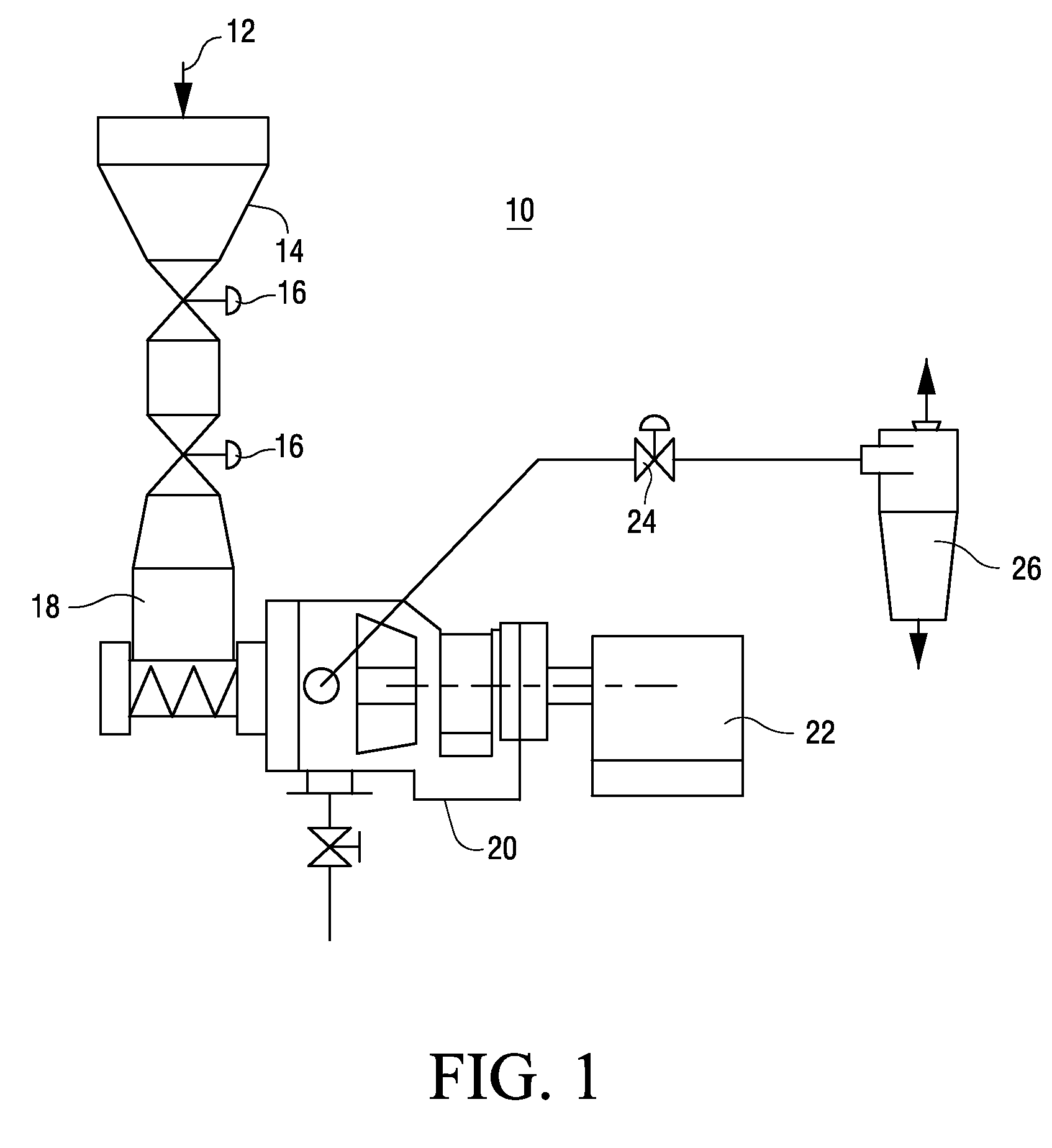
However, it is believed that the estimation of efficiencies as high as 40-60% is in error because evidently more than 90% of the refining energy used in thermo-mechanical pulps (TMP) is converted into heat.

Method used


Image

  • Method and system for energy savings in TMP by high temperature LC/MC refining of pulp
  • Method and system for energy savings in TMP by high temperature LC/MC refining of pulp
  • Method and system for energy savings in TMP by high temperature LC/MC refining of pulp

Examples


first embodiment

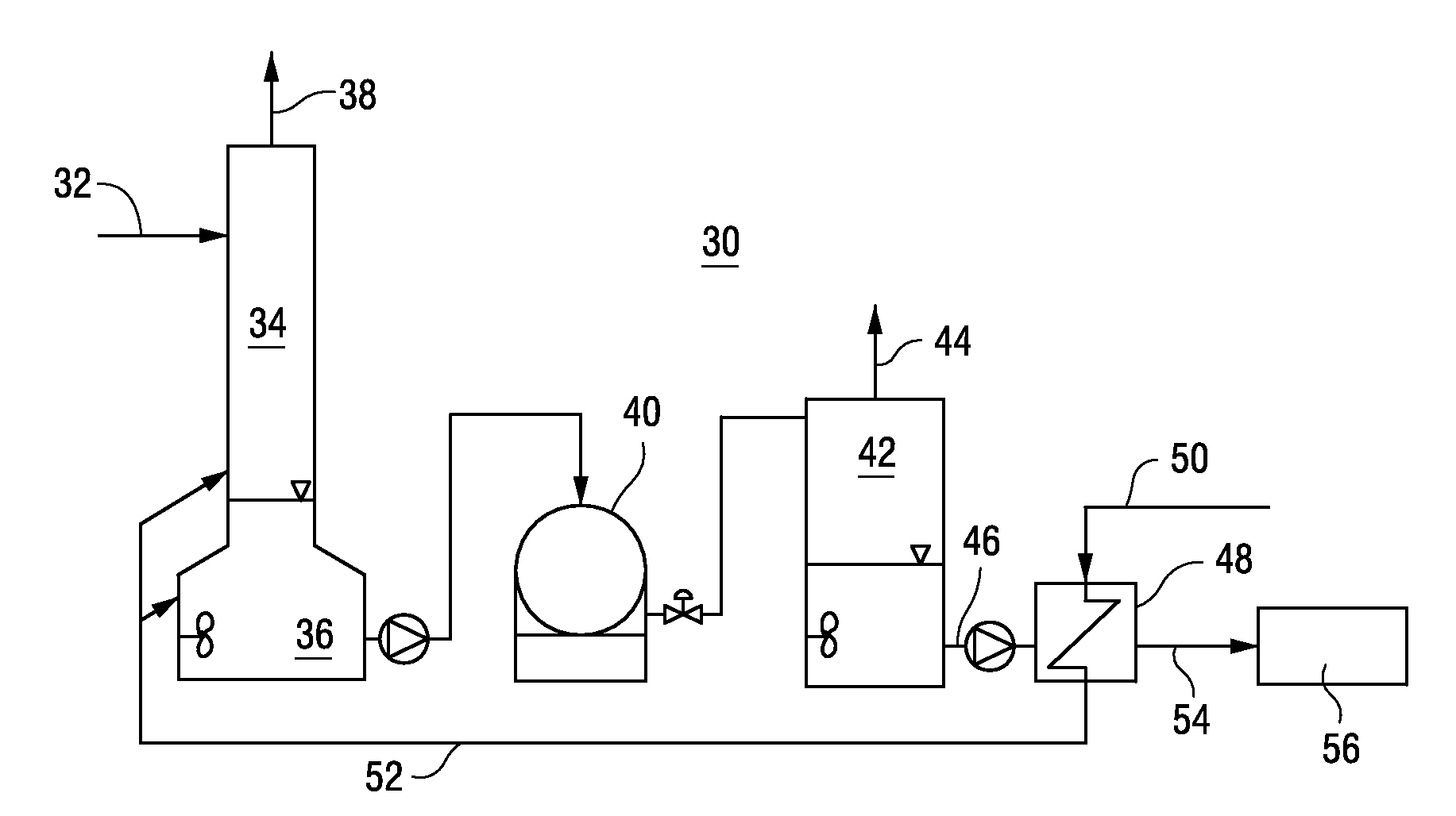
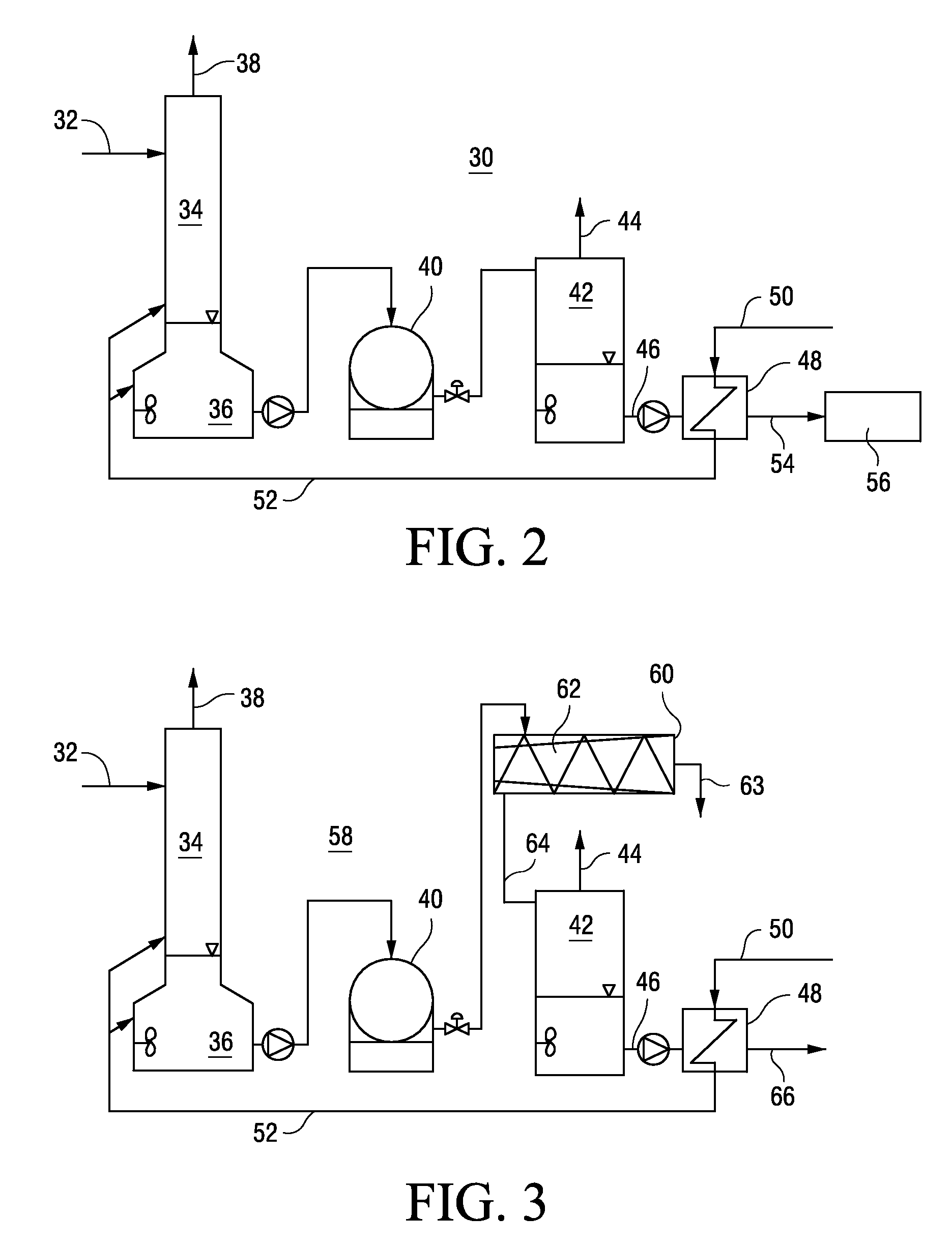
[0032]FIG. 2 is a flow sheet for a pulp refining plant 30 that recovers high pressure steam from flash tanks. The plant 30 improves the optimization of the overall heat balance in the plant by recovering a major portion of the energy applied in the LC or MC stage in the form of steam.

[0033]From a blowline 32 of a primary pressurized refiner (see e.g., blowline 24 and refiner 20 in FIG. 1), fibers are discharged into a pressurized cyclone 34, which is sealed at the bottom by a water-lock or liquid phase separator 36. Liquid phase separators are used in several North American TMP plants. In the upper portion of the cyclone 34, steam 38 is separated from the fibers and led to the heat recovery system (not shown). Some of the steam 38 may be utilized to heat dilution water to about 140° C., which is pumped to the water-lock at the bottom of the cyclone.

[0034]From the water-lock 36, hot pulp is pumped, at about 4% to 5% consistency, to a low consistency refiner 40. The refiner may be pow...

second embodiment

[0039]FIG. 3 is a flow sheet for a pulp refining plant 58 that recovers high pressure steam from flash tanks. To the extent that the plant 58 in FIG. 3 has components in common with the plant 30 shown in FIG. 2, similar reference numerals have been used in both figures.

[0040]The flow chart of FIG. 3 shows an alternate process 58 (to that shown in FIG. 2) that also involves pulp washing. The process 58 shown in FIG. 3 may be applied in a MC refining process and the process 30 (FIG. 2) may be applied in a LC refining process. A difference between the two processes, is that pulp flows through a flash tank and heat exchanger in process 30 but not in process 58.

[0041]In process 58, a pressurized pulp slurry flows form the pressurized cyclone 34 with the water-lock 36, and is pumped preferably at medium consistency (MC) to a refiner 40. The MC pulp flows from the refiner to a screw-press 60 having a pressurized pressate collection mantle 62. The hot fiber pressate 63 from the screw-press ...


PUM

PropertyMeasurementUnit
pressureaaaaaaaaaa
temperatureaaaaaaaaaa

Abstract

A method for recovering heat from a pulp refining process comprising: discharging pressurized pulp from a high pressure refiner, wherein the pressurized pulp comprises a pressurized slurry of fibers and liquid; introducing at least the liquid from the pressurized pulp slurry to a pressurized flash tank; exchanging heat from the pressurized flash tank with water, such that the water is heated, and using the heated water in the pulp refining process.

Description

[0001]This application claims the benefit of U.S. Provisional Application Ser. No. 60 / 686,934, filed Jun. 3, 2006, which provisional application is incorporated by reference in its entirety.BACKGROUND OF THE INVENTION[0002]Energy savings in mechanical pulping are highly desirable from an economical and ecological perspective and could significantly contribute to improve the overall competitiveness of the Paper and Board Industry.[0003]One method to reduce the energy requirements of conventional thermo-mechanical pulping (TMP) without sacrificing pulp quality is low consistency (LC) refining at 70° C. to 90° C. right after the latency chest. This method typically achieves only a 5% to 8% specific energy reduction. Further, the method typically causes significant fiber shortening and loss of tear strength. Chemo-mechanical pulps (CMP) and chemo-thermo-mechanical pulps (CTMP) provide much higher potential for energy savings by LC refining because their lignin softening temperature is l...

Claims


Application Information

Patent Timeline
Patent Type & Authority Patents(United States)
IPC IPC(8): D21C11/06
CPCD21B1/12D21C3/22D21C9/007D21D1/20Y02P70/10
Inventor MUNSTER, HEINRICH
Owner ANDRITZ AG
Learn More