Wire bond and redistribution layer process

a technology of redistribution layer and wire bonding, which is applied in the direction of semiconductor devices, semiconductor/solid-state device details, electrical devices, etc., can solve the problem that devices must consume very little space, and achieve the effect of increasing the efficiency of semiconductor devices, reducing the size of chips, and reducing the packaging size of chips

Active Publication Date: 2009-06-02
SEMICON COMPONENTS IND LLC
View PDF10 Cites 3 Cited by
  • Summary
  • Abstract
  • Description
  • Claims
  • Application Information

AI Technical Summary

Benefits of technology

[0004]One way of increasing the efficiency of a semiconductor device is to decrease the packaging size of the chip. One feature of this invention provides for process technology which allows for the integration of inductors with the integrated circuit on a single die, resulting in the overall decreased size of the chip.
[0005]Performance of the resulting device will also be better since the integrated circuit is near the die which is the source of action or execution. In addition, the SMT manufacturing will be easier as less passive devices are assembled onto the board. The cost of the SMT manufacturing process can also assist in decreasing the size of the mother board.
[0006]Another feature of this invention is that the use of aluminum for the wire bond pads results in a simpler manufacturing process and lowers the cost of manufacturing. Aluminum is a standard assembly feature and requires no special handling. Thus, the use of aluminum wire bonds results in a simpler manufacturing process. In addition, the use of aluminum wire bond pads instead of copper wire bond pads lowers the cost of manufacturing.
[0007]The use of aluminum wire bond pads instead of copper wire bond pads also results in the prevention of deterioration of the resulting device. Aluminum does not oxide as quickly as copper. Thus, the use of aluminum wire bond pads prevents the deterioration and oxidation of the wire bond pads.
[0008]In mobile devices, this invention has several additional features. One feature is that the device can provide ESD protection in the range of + / −15 kilo electron volt (IEC) to + / −30 kilo electron volt (HBM). Another feature of this device is that it can provide filtering in the range of 3 gigahertz to 10 gigahertz.

Problems solved by technology

Further, these devices must consume very little space.

Method used


Image

  • Wire bond and redistribution layer process
  • Wire bond and redistribution layer process
  • Wire bond and redistribution layer process

Examples


Embodiment Construction

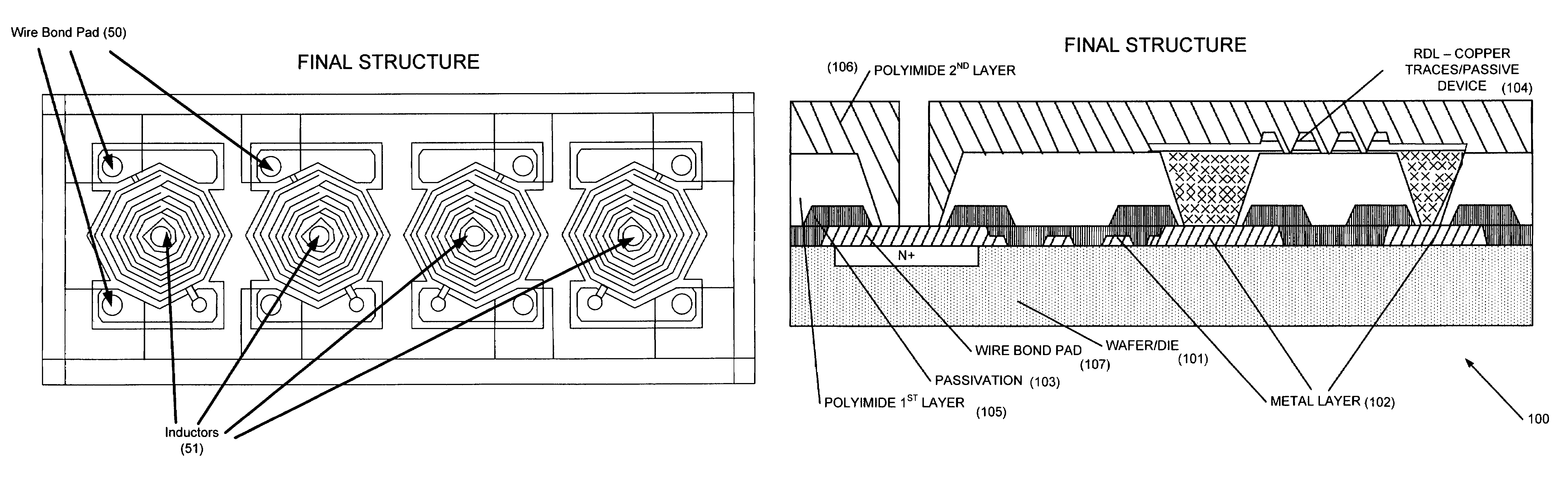
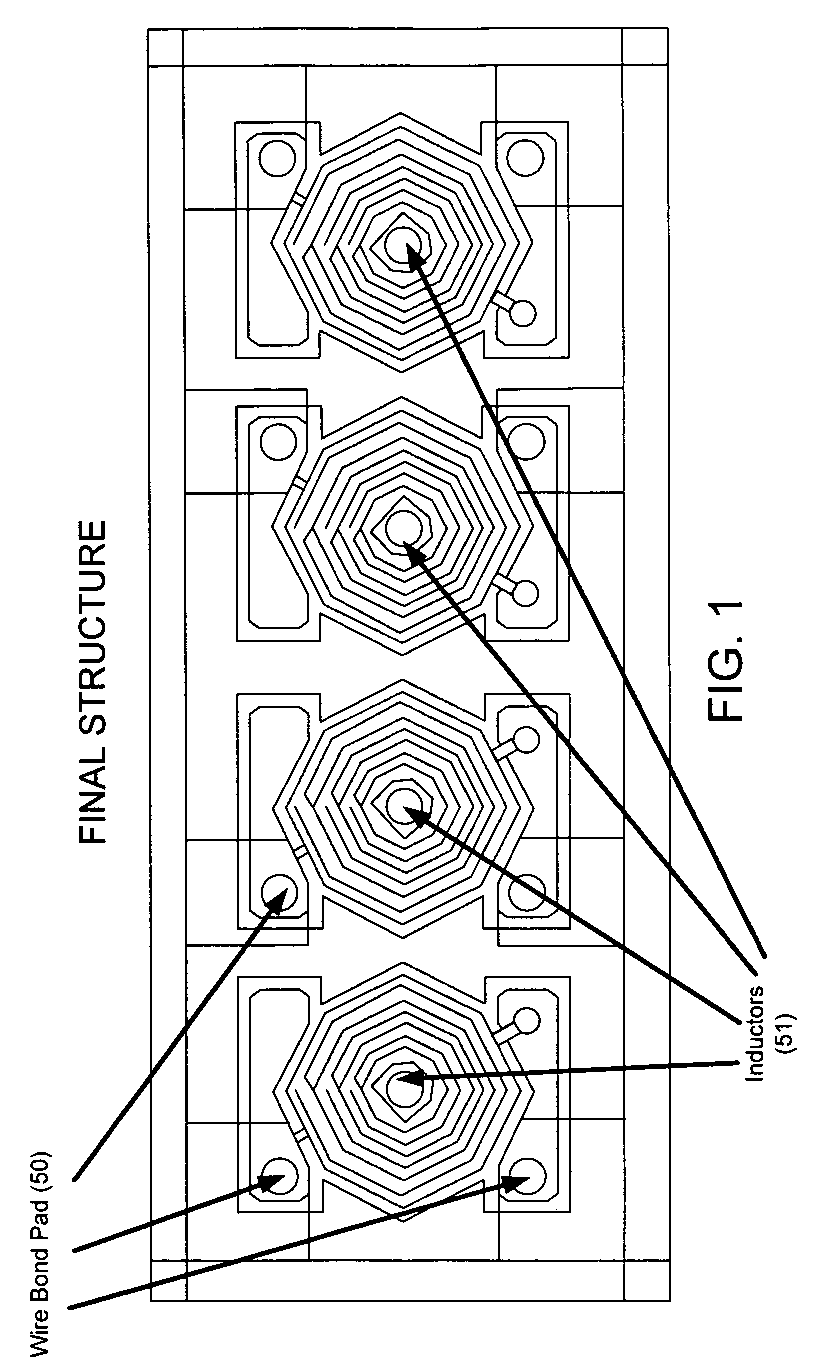
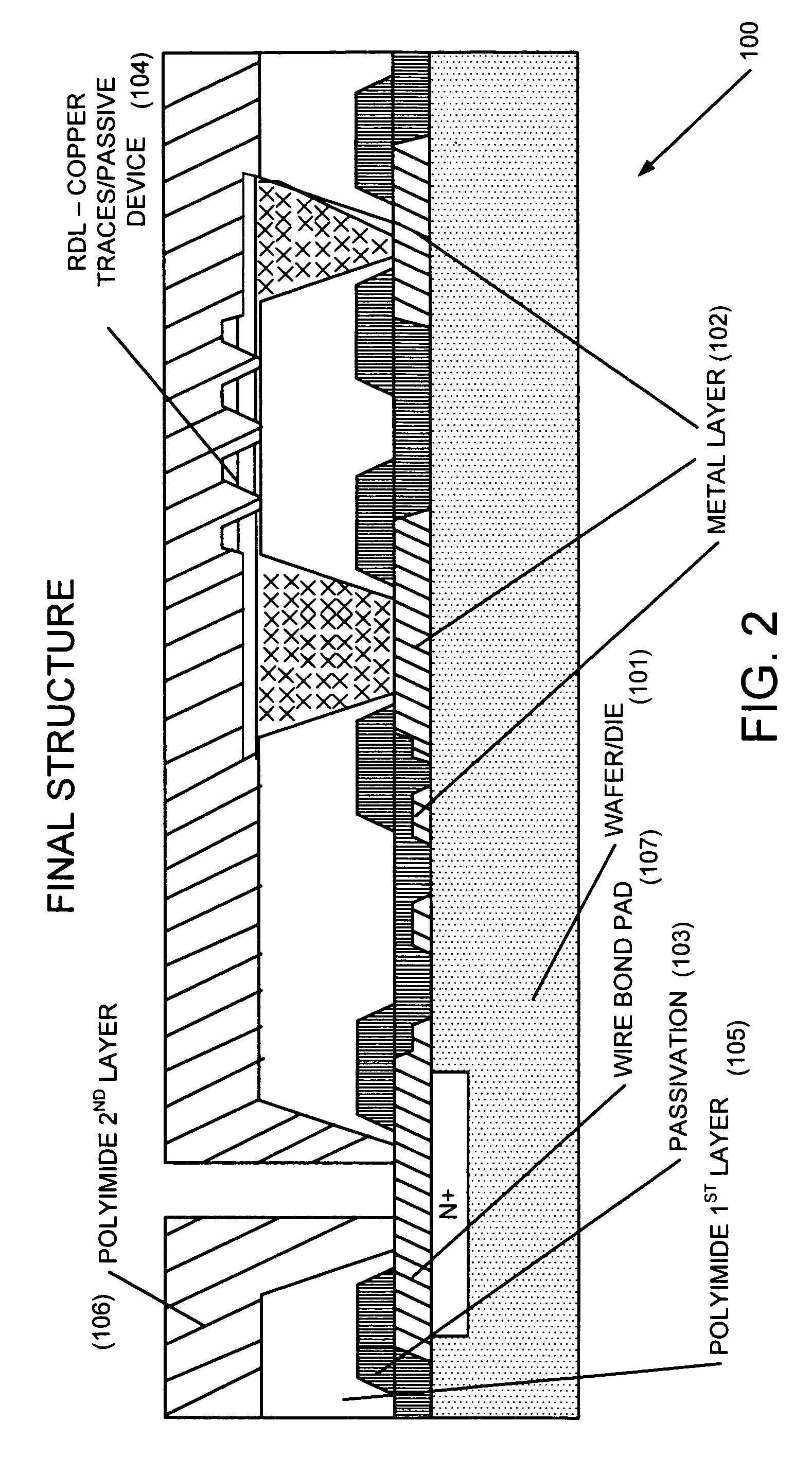
[0012]Embodiments of the present invention will now be described in detail with reference to the drawings, which are provided as illustrative examples so as to enable those skilled in the art to practice the invention. Notably, the figures and examples below are not meant to limit the scope of the present invention. Wherever convenient, the same reference numbers will be used throughout the drawings to refer to same or like parts. Where certain elements of these embodiments can be partially or fully implemented using known components, only those portions of such known components that are necessary for an understanding of the present invention will be described, and detailed descriptions of other portions of such known components will be omitted so as not to obscure the invention. Further, the present invention encompasses present and future known equivalents to the components referred to herein by way of illustration.

[0013]FIG. 1 shows a top view of the final structure of an embodim...


PUM


Abstract

A manufacturing method of a semiconductor device with a copper redistribution line, a copper inductor and aluminum wire bond pads and the integration of the resulting device with an integrated circuit on a single chip, resulting in the decreased size of the chip.

Description

FIELD OF THE INVENTION[0001]The present invention relates generally to semiconductor devices, more specifically to the manufacturing method of a semiconductor device with metal redistribution layers and wire bond pads.BACKGROUND OF THE INVENTION[0002]Many different processes that include the usage of redistribution layers and wire bond pads are in the literature and patents, including Aiba (U.S. Pat. No. 6,586,273), Tsai (U.S. Pat. No. 6,180,445), Lam (U.S. Pat. No. 6,511,901), Jackson (U.S. Pat. No. 6,800,930) and Chungpaiboonpatana (U.S. Pat. No. 6,674,174). Irrespective of these known processes, further improvements are needed particularly with respect to chips that are used in mobile devices which require significant ESD protection as well as the ability to pass signals at high frequencies. Further, these devices must consume very little space. Also, since these semiconductor devices are incorporated into products that are sold to consumers, the manufacturing cost of the compone...

Claims


Application Information

Patent Timeline
Patent Type & Authority Patents(United States)
IPC IPC(8): H01L21/20
CPCH01L23/5227H01L23/60H01L24/02H01F41/041H01L27/0248H01L2924/01005H01L2924/01013H01L2924/01014H01L2924/01022H01L2924/01028H01L2924/01029H01L2924/01074H01L2924/14H01L2924/19042H01L2924/3011H01L2924/01006H01L2924/01024H01L2224/45124H01L2924/00H01L2224/45147H01L2924/00014H01L2224/48H01L2924/00011H01L24/05H01L2224/04042
Inventor HAMAMOTO, MITCHELL M.CHEN, YIOAOTAN, KIM HWEE
Owner SEMICON COMPONENTS IND LLC
Why Eureka
Try Eureka