Liquid crystal display device

a liquid crystal display and display device technology, applied in non-linear optics, instruments, optics, etc., can solve the problems of spoiled flatness of diffusion plate sct, and element cannot obtain uniform brightness distribution

Inactive Publication Date: 2009-06-02
HITACHI DISPLAYS +1
View PDF33 Cites 25 Cited by
  • Summary
  • Abstract
  • Description
  • Claims
  • Application Information

AI Technical Summary

Benefits of technology

[0023]It is considered that Japanese Laid-open Patent Publication 223812 / 1999 suppresses the drying of the light-source-side surface of the diffusion plate by mounting a transparent sheet on the light-source-side surface of the diffusion plate. However, in such a constitution, it is understood that the transparent sheet is brought into close contact with the diffusion plate. Since this contact is not considered to constitute the adhesion, a gap is formed between the diffusion plate and the transparent sheet although the gap is minute. While the, moisture leaks through this gap, a gap defined between the optical sheet which is laminated to the liquid-crystal-display-element side of the diffusion plate and the diffusion plate is narrower than the gap between the diffusion plate and the light-source-side transparent sheet due to the deadweight of the optical sheet. Further, the circulation of air through the gap defined between the optical sheet which is laminated to the liquid-crystal-display-element side of the diffusion plate and the diffusion plate is smaller than the circulation of air through the gap between the diffusion plate and the light-source-side transparent sheet whose temperature is liable to be elevated faster, the moisture is difficult to escape (difficult to be dried) and hence, the prevention of the projecting of the diffusion plate toward the liquid-crystal-display element side is less than optimal.
[0055]By adhering the diffusion plate to the whole surface of the transparent sheet, the drying of the light-source side of the diffusion plate is remarkably reduced so that a warp of the diffusion plate projecting toward the light-source side can be suppressed. Further, with the provision of the spacer between the light source and the diffusion plate, even when a warp of the diffusion plate which is projected toward the light-source side occurs due to the environment in which the liquid crystal display device is used or the deadweight of the diffusion plate, the brightness distribution of the illumination light irradiated to the liquid crystal display element can be uniformly held.

Problems solved by technology

However, since the diffusion plate SCT is arranged close to the cold cathode fluorescent lamps CFL, when a given time elapses after the cold cathode fluorescent lamps CFL are turned on, a warp which forms the diffusion plate SCT in a projected form toward the liquid crystal display element side, for example, is generated so that there is a possibility that the flatness of the diffusion plate SCT is spoiled.
When the flatness of the diffusion plate SCT is spoiled, the brightness distribution adjustment using the reflection light shielding pattern formed on the diffusion plate SCT gives rise to irregularities so that the illumination light irradiated to the liquid crystal display element cannot obtain the uniform brightness distribution.

Method used


Image

  • Liquid crystal display device
  • Liquid crystal display device
  • Liquid crystal display device

Examples


first embodiment

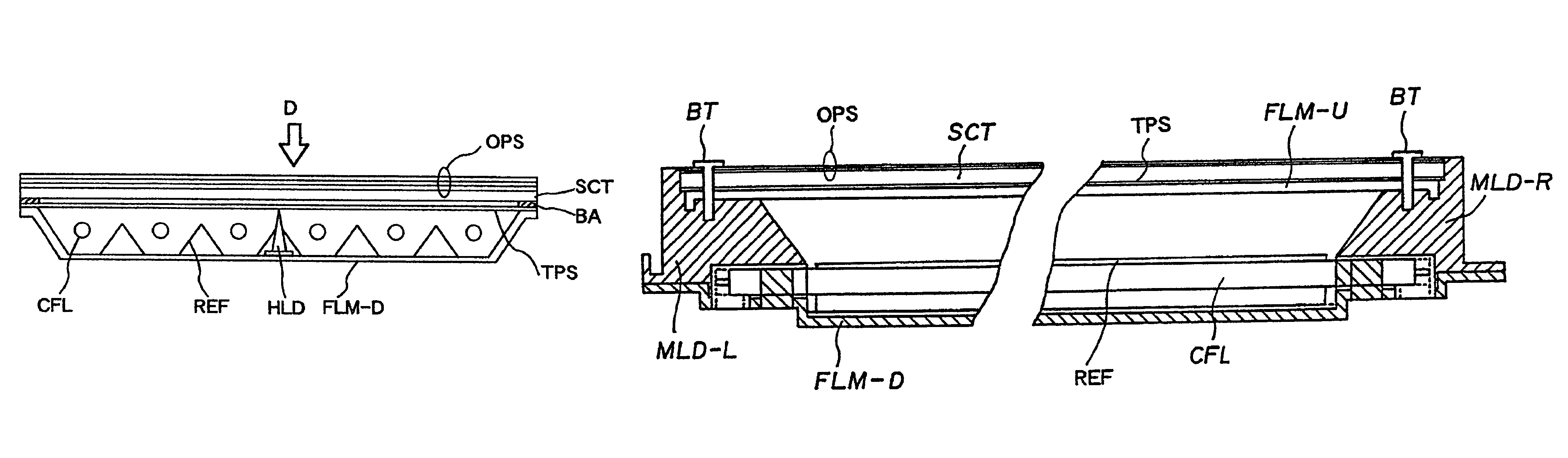
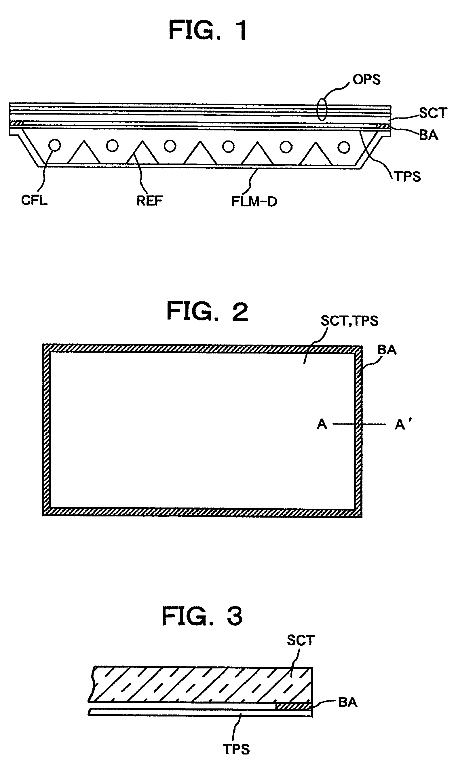
[0073]FIG. 1 is a cross-sectional view of a direct backlight for schematically explaining a liquid crystal display device according to the present invention, FIG. 2 is a plan view for schematically explaining the adhering state of a diffusion plate and a transparent sheet shown in FIG. 1, and FIG. 3 is a partial cross-sectional view taken along a line A-A′ in FIG. 2.

[0074]Here, although a liquid crystal display element is arranged above the direct backlight shown in FIG. 1, such a liquid crystal display element is omitted from the drawings.

[0075]In FIG. 1, the direct backlight of this embodiment is constituted by arranging a diffusion plate SCT having a relatively large thickness (approximately 2 mm, for example) formed of acrylic resin (or possibly polycarbonate resin) above and close to a plurality of cold cathode fluorescent lamps CFL which constitute a light source. The diffusion plate SCT is formed of a rectangular plate in the same manner as the liquid crystal display element....

third embodiment

[0085]In the liquid crystal display device according to the present invention, a tacky adhesive agent is coated on the whole surfaces of the diffusion plate SCT and the transparent sheet TPS which face each other in an opposed manner using means similar to the means described above and then they are laminated to each other by adhesion.

[0086]Also according to this embodiment, the drying conditions at the optical sheet side and the transparent sheet side of the diffusion plate can be made substantially equal so that it becomes possible to prevent the occurrence of the warp of the diffusion plate whereby the luminance distribution of the illumination light to the liquid crystal display element can be held uniform.

fourth embodiment

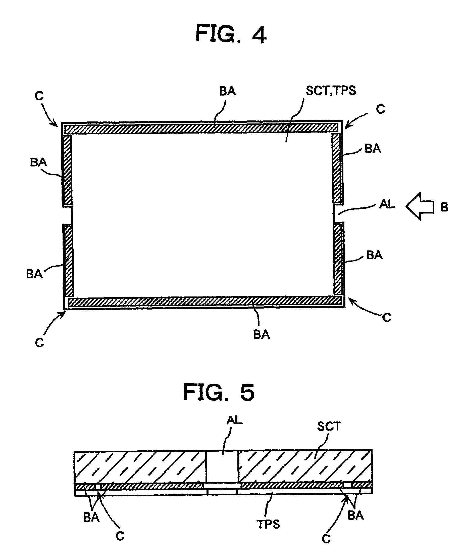
[0087]In the liquid crystal display device according to the present invention, the whole peripheries formed between the whole four sides of the diffusion plate SCT and a transparent sheet TPS are adhered to each other using a pressure sensitive adhesive double-coated tape BA. At the same time, a tacky adhesive agent is coated on the whole surfaces of the diffusion plate SCT and the transparent sheet TPS which face each other in an opposed manner so as to laminate them by adhesion using means similar to the above-mentioned means.

[0088]Also according to this embodiment, the drying conditions at the optical sheet side and the transparent sheet side of the diffusion plate can be made substantially equal so that it becomes possible to prevent the occurrence of the warp of the diffusion plate whereby the luminance distribution of the illumination light to the liquid crystal display element can be held uniform.


PUM

PropertyMeasurementUnit
thicknessaaaaaaaaaa
thicknessaaaaaaaaaa
lengthaaaaaaaaaa

Abstract

In a liquid crystal display device, a transparent sheet TPS is provided to a surface of a diffusion plate SCT which faces a light source (cold cathode fluorescent lamps CFL). The whole or at least respective portions of four sides forming peripheries of the transparent sheet TPS and the diffusion plate SCT are adhered to each other using a pressure sensitive adhesive double-sided tape or the like thus sealing a gap defined between them in a complete state or in an incomplete state with respect to outside air so that the drying conditions at a liquid-crystal-display element side and a light-source side of the diffusing plate SCT become equal.

Description

CROSS-REFERENCE TO RELATED APPLICATIONS[0001]This application is a Continuation of U.S. application Ser. No. 10 / 055,969 filed Jan. 28, 2002, now abandoned, and claims priority to U.S. application Ser. No. 10 / 055,969 filed Jan. 28, 2002, which claims priority to Japanese Patent Application No. 2001-039522 filed on Feb. 16, 2001, all of which is incorporated by reference.BACKGROUND OF THE INVENTION[0002]1. Field of the Invention[0003]The present invention relates to a liquid crystal display device mounting a direct light source on a liquid crystal display element, and more particularly, to a liquid crystal display device which can irradiate the illumination light of the uniform brightness with respect to the liquid crystal display element by suppressing a warp of a diffusion plate which is arranged between the direct light source and the liquid crystal display element.[0004]2. Description of the Related Art[0005]There has been known a liquid crystal display device which is provided wi...

Claims


Application Information

Patent Timeline
Patent Type & Authority Patents(United States)
IPC IPC(8): G02F1/1335G02F1/1333G02F1/13357
CPCG02F1/133604G02F1/133605G02F1/133608G02F1/133504G02F2201/54G02F2202/28G02F1/1335
Inventor SAITO, KENISHIDA, KAZUHIRO
Owner HITACHI DISPLAYS
Why Eureka
Try Eureka