Image display method, image display device, and projector

a display method and image technology, applied in the field of image display methods, can solve the problems of increasing the load of the arithmetic processor, the image is darker, and the flickering image may also be painful to the eyes of the observer, so as to suppress the increase of the signal processing load, suppress the blur of the displayed image, and improve the display quality

Active Publication Date: 2009-06-02
SEIKO EPSON CORP
View PDF31 Cites 29 Cited by
  • Summary
  • Abstract
  • Description
  • Claims
  • Application Information

AI Technical Summary

Benefits of technology

[0016]An advantage of some aspects of the invention is to suppress an increase in the signal processing load while also suppressing the blur of the displayed image. Another advantage of some aspects of the invention is to provide an image display method which can achieve visual characteristics similar to those of the natural world, and an image display method and a projector which obtain excellent display quality.

Problems solved by technology

However, the method (1) of intermittent image display in a continuous-type image display device includes a black display period, which leads to a problem in that the image is darker than in heretofore continuous-type image display devices.
The flickering image may also be painful to eyes of an observer.
The method (2) of image display by doubling the frame frequency of the input image signal and inserting a generated image signal has a problem that, since a new image signal is generated by calculating the motion vector and the like after precisely capturing the movement of the moving object, the load of the arithmetic processor greatly increases.
Moreover, since an error in the generated image will cause flickering, the new image signal must be generated with high precision.
While the methods of (1) and (2) reduce the blur of the outline of a moving object when tracked by the line of sight, they have difficulties in solving the above problems.
In each method, the outline of the moving object is visible even when not tracked by the line of sight, leading to a problem that the display is unnatural.

Method used


Image

  • Image display method, image display device, and projector
  • Image display method, image display device, and projector
  • Image display method, image display device, and projector

Examples


first embodiment

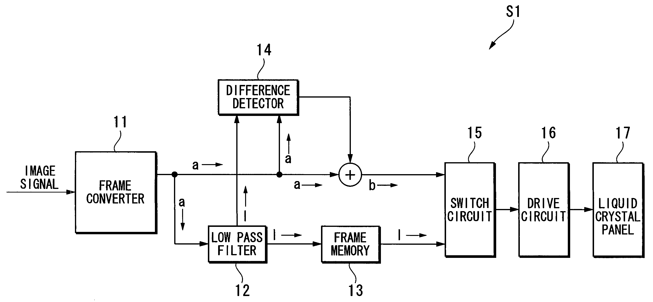
[0079]Image Display Device

[0080]FIG. 1 is a block diagram of the functional configuration showing an image display device S1 according to a first embodiment. As shown in FIG. 1, the image display device S1 of this invention includes a frame converter 11, a low-pass filter 12 (high-spatial frequency component reducing unit), a frame memory 13, a difference detector 14 (high-spatial frequency component increasing unit), a switch circuit 15, a drive circuit 16, and a liquid crystal panel 17.

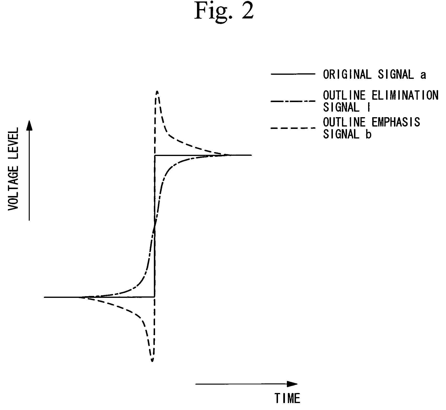
[0081]The frame converter 11 divides one frame into two sub-frames by doubling (e.g., to 120 Hz) the frame frequency (e.g., 60 Hz) of an image signal which is input thereto from the outside. In the following explanation, an image signal which has been frame converted by the frame converter 11, i.e., an image signal which is output from the frame converter 11, is termed an original signal “a”.

[0082]The low-pass filter 12, which is connected to the frame converter 11, reduces the high-spatial frequenc...

second embodiment

[0110]Image Display Device

[0111]FIG. 2 is a block diagram showing an image display device according to a second embodiment.

[0112]The image display device according to this embodiment mainly includes a liquid crystal device 100 and a display controller 290. The liquid crystal device 100 includes a drive circuit 110D which drives a liquid crystal panel 110. The drive circuit 110D includes a semiconductor IC chip which is mounted directly on the liquid crystal panel 110, a semiconductor IC chip which is mounted on a circuit board conductively connected to the liquid crystal panel 110, or such like. The drive circuit 110D includes a scanning line drive circuit, a signal line drive circuit, and a check circuit.

[0113]The display controller 290 mainly includes a display information output source 291, a display information processor 292, and a timing generator 294.

[0114]The display information output source 291 includes a memory consisting of a read only memory (ROM), a random access memory...

third embodiment

[0151]Subsequently, a third embodiment of this invention will be explained using FIG. 9 through FIG. 11.

[0152]FIG. 9 is a block diagram showing a processor according to the third embodiment. FIG. 9 depicts only the parts of the processor 292 shown in FIG. 4 which are characteristic features of this invention. The image display method according to the third embodiment includes determining the application rate of a secondary intermediate image signal and the application rate of a primary intermediate image signal based on the difference between continuous frames of input image signals, and synthesizing the first and secondary intermediate image signals in accordance with their determined application rates, and generating a generated image signal. Repetitious explanation of parts which are the same as those in the second embodiment will be omitted.

[0153]Image Display Device

[0154]As shown in FIG. 9, a mask generator 330 is connected to the memory controller 314. The mask generator 330 g...


PUM


Abstract

An image display method includes dividing one frame into a plurality of sub-frames by multiplying a frame frequency of an input image signal, reducing a high-spatial frequency component of an image signal which is used for image display in at least one predetermined sub-frame among the plurality of sub-frames in comparison with that of an image signal which is used for image display in another sub-frame, and displaying an image in each sub-frame.

Description

CROSS-REFERENCE TO RELATED APPLICATION[0001]This application claims priority to Japanese Patent Application No. 2004-349652, filed Dec. 2, 2004, Japanese Patent Application No. 2005-040414, filed Feb. 17, 2005, and Japanese Patent Application No. 2004-349653, filed Dec. 2, 2004, the contents of which are incorporated herein by reference.BACKGROUND[0002]1. Technical Field[0003]The present invention relates to an image display method, an image display device, and a projector.[0004]2. Related Art[0005]An image display device such as a television displays an image in each frame. For example, at a frame frequency of 60 Hz, an image of an object is displayed at a slightly different position in each frame to produce a moving image of the movement of the object.[0006]FIG. 14 Part A through FIG. 17 Part A show display images in each frame of a moving image of a moving object, time being represented by the vertical axis. FIG. 14 Part B through FIG. 17 Part B are views of a moving object when ...

Claims


Application Information

Patent Timeline
Patent Type & Authority Patents(United States)
IPC IPC(8): G06K9/40G09G5/00
CPCG09G3/2092G09G2320/02G09G2320/0261G09G2320/10G09G3/02G09G3/20
Inventor TOYOOKA, TAKASHIYOSHIDA, SHOHEI
Owner SEIKO EPSON CORP
Why Eureka
Try Eureka