Method and apparatus for predicting unsteady pressure and flow rate distribution in a fluid network

a fluid network and flow rate technology, applied in the field of simulation modeling, can solve problems such as inability to extend the capability of simulation codes, time-consuming and inefficient changes, and use simulation codes for new designs

Inactive Publication Date: 2009-06-02
NASA
View PDF5 Cites 39 Cited by
  • Summary
  • Abstract
  • Description
  • Claims
  • Application Information

AI Technical Summary

Problems solved by technology

Because of the confidential proprietary nature of computer codes, it is not possible to extend their capability to satisfy other than the above mentioned conditions.
Yet another limitation is that simulation code for fluid networks is traditionally for a specific purpose and for specific flow systems, such as to model the Space Shuttle Main Engine (SSME) turbopump.
It is difficult to use simulation codes for new designs without making extensive changes in the original code, these changes can prove to be time consuming and inefficient.
However, as computers allowed much larger networks to be analyzed, it became apparent that the convergence of the Hardy Cross method might be very slow or even fail to provide a solution in some cases.
The main reason for this numerical difficulty is that the Hardy Cross method does not solve the system of equations simultaneously.
It is evident that the Hardy Cross method belongs in the category of successive substitution methods, and it is therefore likely that it may encounter convergence difficulties for large circuits.
Naiver-Stokes methods, however, are not particularly suitable for modeling flow distribution in a complex network.
These are not suitable for modeling rocket engine turbopumps where mixing, phase change and rotational effects are present.
However, composite fluids, phase changes and rotational effects have proven difficult to model and simulate using existing software.

Method used


Image

  • Method and apparatus for predicting unsteady pressure and flow rate distribution in a fluid network
  • Method and apparatus for predicting unsteady pressure and flow rate distribution in a fluid network
  • Method and apparatus for predicting unsteady pressure and flow rate distribution in a fluid network

Examples


Embodiment Construction

[0025]In the following detailed description, reference is made to the accompanying drawings that form a part hereof, and in which is shown by way of illustration specific embodiments that may be practiced. These embodiments are described in sufficient detail to enable those skilled in the art to practice the embodiments, and it is to be understood that other embodiments may be utilized and that logical, mechanical, electrical and other changes may be made without departing from the scope of the embodiments. The following detailed description is, therefore, not to be taken in a limiting sense.

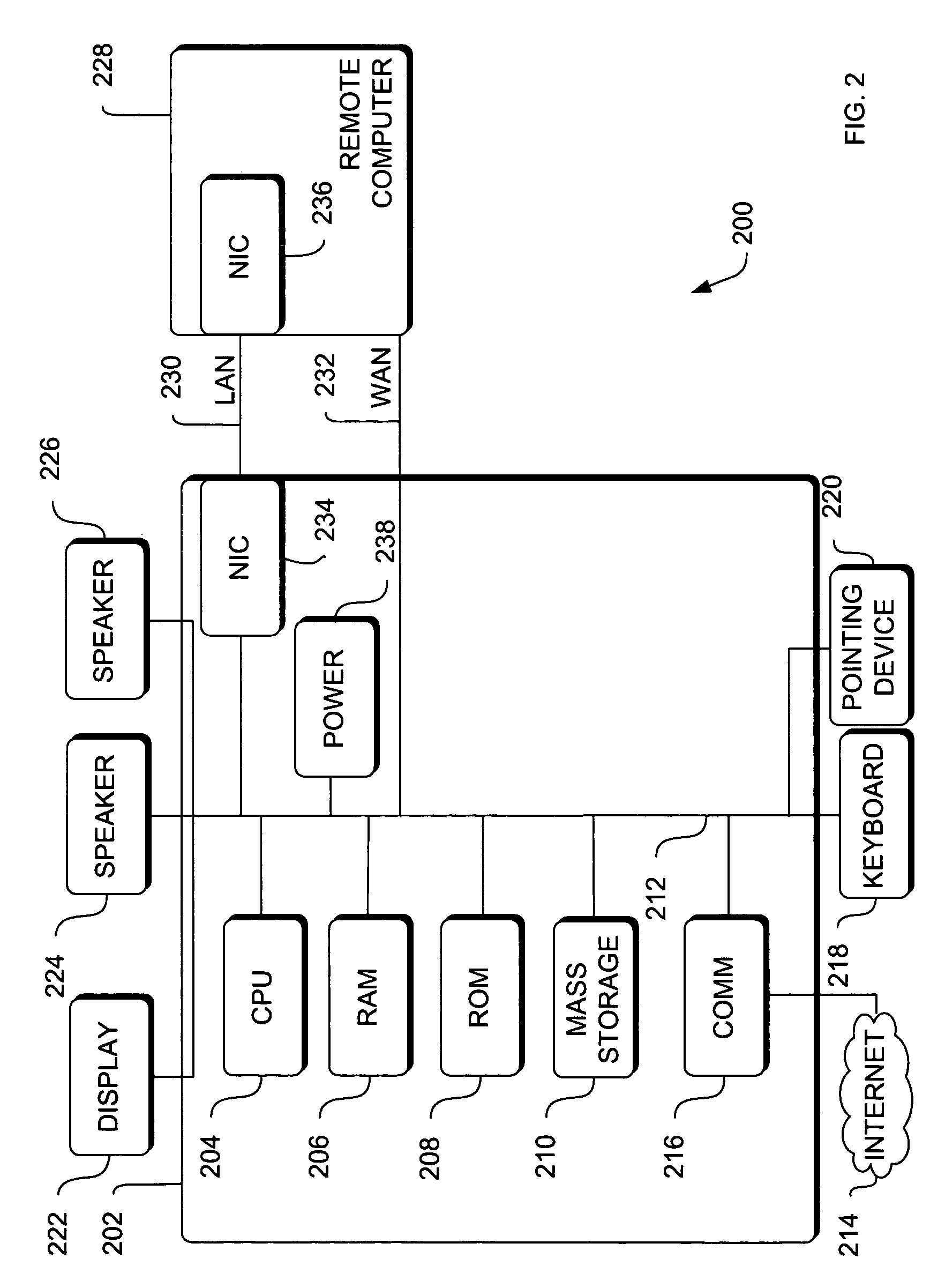
[0026]A system level overview of the operation of an embodiment will be described with reference to FIG. 2. In this section, the particular methods performed by the server and clients of such an embodiment are described by reference to flowcharts. Describing the methods by reference to a flowchart enables one skilled in the art to develop such programs, firmware, or hardware, including such inst...


PUM


Abstract

A method and apparatus for analyzing steady state and transient flow in a complex fluid network, modeling phase changes, compressibility, mixture thermodynamics, external body forces such as gravity and centrifugal force and conjugate heat transfer. In some embodiments, a graphical user interface provides for the interactive development of a fluid network simulation having nodes and branches. In some embodiments, mass, energy, and specific conservation equations are solved at the nodes, and momentum conservation equations are solved in the branches. In some embodiments, contained herein are data objects for computing thermodynamic and thermophysical properties for fluids. In some embodiments, the systems of equations describing the fluid network are solved by a hybrid numerical method that is a combination of the Newton-Raphson and successive substitution methods.

Description

RELATED APPLICATION[0001]This application is a continuation-in-part (CIP) of U.S. patent application Ser. No. 10 / 863,841, filed Jun. 6, 2004, now abandoned which is a continuation of U.S. patent application Ser. No. 09 / 313,576, filed May 7, 1999, now U.S. Pat. No. 6,748,349. This application incorporates each of its parent applications by reference.ORIGIN OF THE INVENTION[0002]The invention described herein was made by an employee of the United States Government and may be manufactured and used by or for the Government of the United States of America for governmental purposes without the payment of any royalties thereon or therefore.FIELD OF THE INVENTION[0003]The present invention pertains generally to the field of simulation modeling. More specifically, the present invention relates to methods of representing, accessing, inputting, modifying and monitoring parameters of objects describing fluid transient behavior in a complex pipe network.BACKGROUND OF THE INVENTION[0004]A fluid f...

Claims


Application Information

Patent Timeline
Patent Type & Authority Patents(United States)
IPC IPC(8): G06F17/50G05B19/05
CPCG06F17/5018G06F2217/16G06F2217/34G06F2217/78G06F2217/80G06F2113/14G06F30/23G06F2119/08G06F2111/10G06F2119/06
Inventor MAJUMDAR, ALOK K.
Owner NASA
Why Eureka
Try Eureka