Delivery system with low longitudinal compressibility

a delivery system and longitudinal compression technology, applied in the field of medical devices, can solve the problems of not generally compressible, increased risk of coronary bypass surgery, and a long recovery time for patients, and achieve the effect of precise placement of implantable medical devices

Active Publication Date: 2009-11-12
COOK MEDICAL TECH LLC
View PDF13 Cites 98 Cited by
  • Summary
  • Abstract
  • Description
  • Claims
  • Application Information

AI Technical Summary

Benefits of technology

[0012]Delivery systems are described which may allow for more precise placement of implantable medical devices. The delivery systems include a retention sheath that houses and restrains the implantable medical device, and a plurality of separate abutting rings disposed within the retention sheath in a stacked co-axial configuration. The plurality of separate rings may extend from a proximal end of the retention sheath to a proximal end of the implantable medical device. When the retention sheath is moved from a pre-deployment position to a deployment position, the proximal end of the implantable medical device contacts a ring in the plurality of rings located closest to the proximal end of the implantable medical device, and the plurality of separate abutting rings prevents the implantable medical device from moving axially toward the proximal end of the retention sheath. Additional details and advantages are described below in the detailed description.

Problems solved by technology

However, coronary bypass surgery is a very invasive procedure that presents increased risk and requires a long recovery time for the patient.
However, other types of stents are designed to have a fixed diameter and are not generally compressible.
However, it is also possible for aneurysms to form in blood vessels throughout the vasculature.
If not treated, an aneurysm may eventually rupture, resulting in internal hemorrhaging.
In many cases, the internal bleeding may be so massive that a patient can die within minutes of an aneurysm rupture.

Method used


Image

  • Delivery system with low longitudinal compressibility
  • Delivery system with low longitudinal compressibility
  • Delivery system with low longitudinal compressibility

Examples


Embodiment Construction

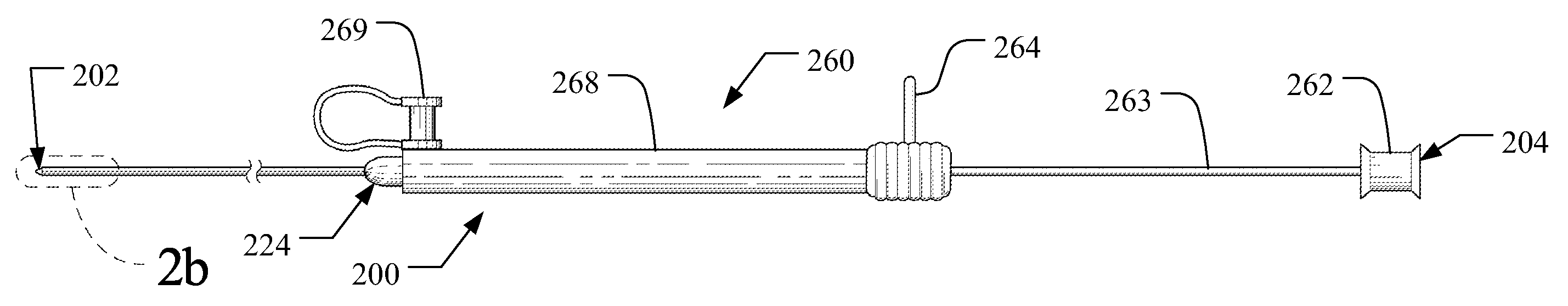
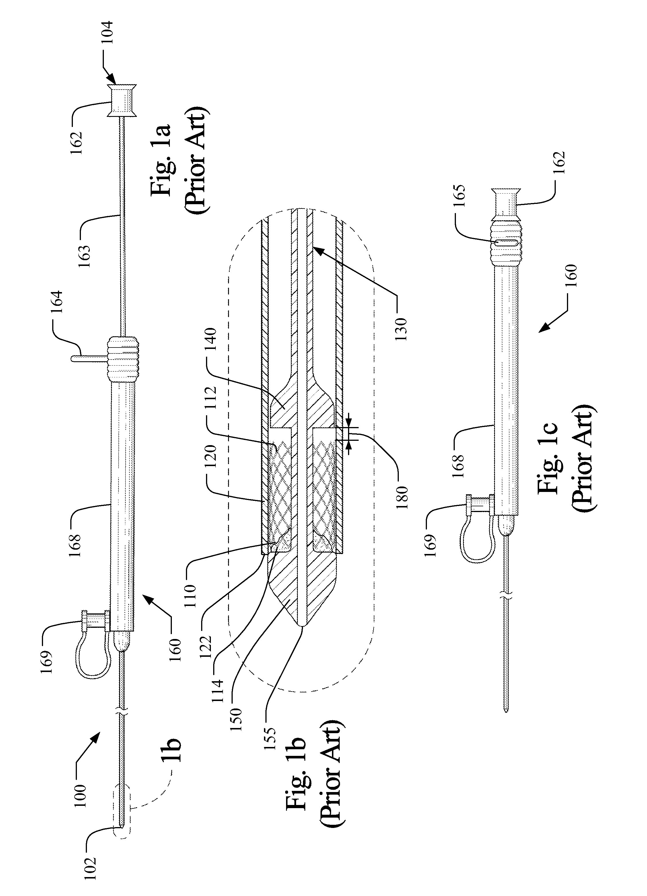
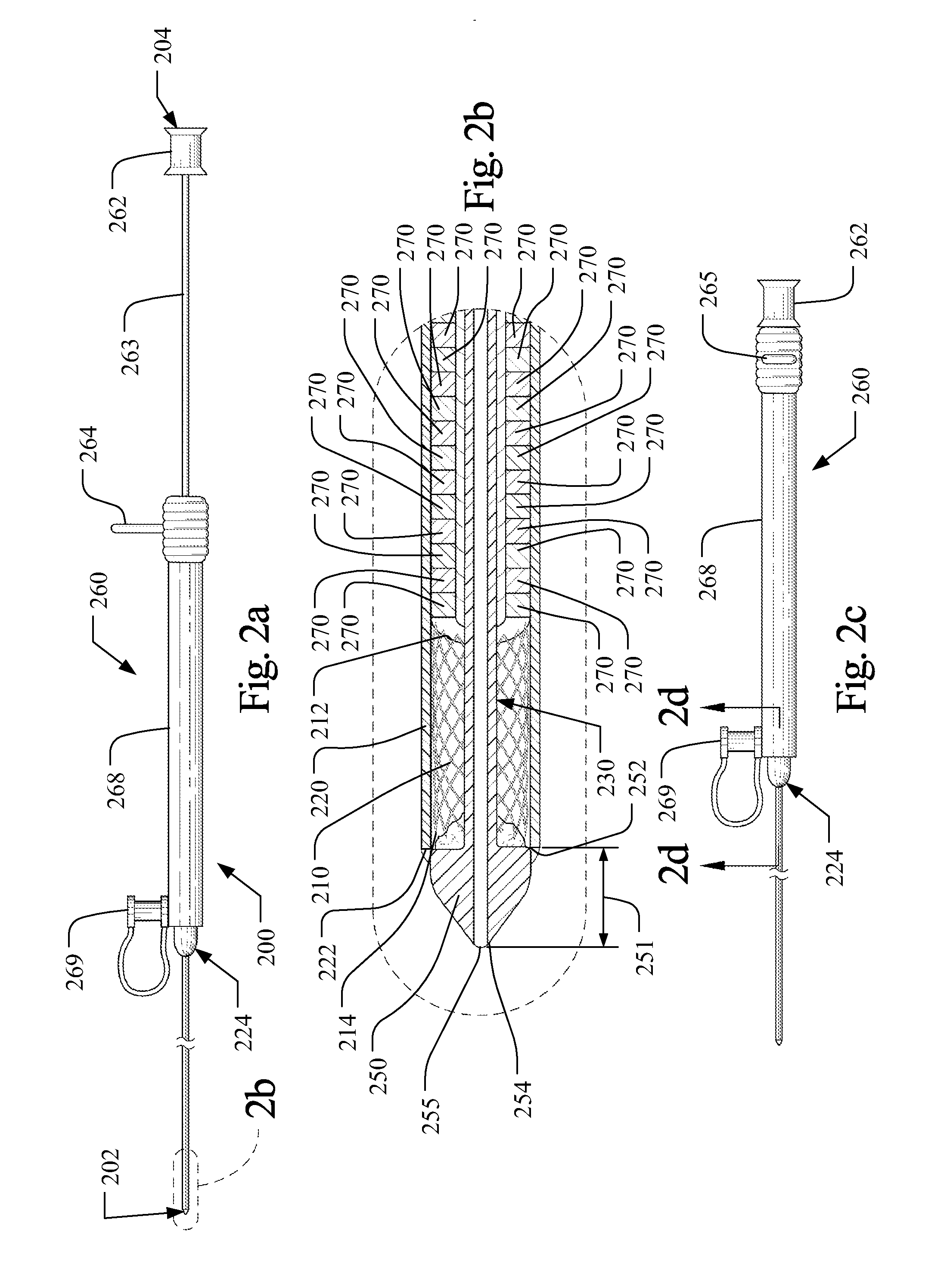
[0039]The term “axial” refers to the lengthwise direction 1 between the distal end 102 and the proximal end 104 of an implantable medical device delivery system 100. The axial direction is aligned with a central axis of the delivery system as shown in the Figures, and denoted as line x-x in FIG. 6(b). The term “distal” and variations thereof refer to the position or orientation relative to the distal end 102, 202 of an implantable medical device delivery system, which is configured to receive a guidewire and be inserted into a patient's vasculature, while the term “proximal” and variations thereof refer to the position or orientation relative to the proximal end 104, 204 of the delivery system 100, 200, as shown in FIGS. 1(a) and 2(a). The term implantable medical device refers to medical devices capable of being implanted within a human being including, for example and without limitation, self-expanding stents, balloon expanding stents, coils, filters, valves, baskets, and endovasc...


PUM


Abstract

An improved delivery system for an implantable medical device includes a retention sheath having a proximal end, a distal end, and an inner lumen extending from the proximal end to the distal end. The implantable medical device is disposed within the inner lumen of the retention sheath, which restrains the implantable medical device. A plurality of substantially incompressible rings are disposed within the inner lumen of the retention sheath in a stacked co-axial configuration that extends from the proximal end of the retention sheath in a pre-deployment position to a proximal end of the implantable medical device. Each ring in the plurality of separate rings abuts at least a portion of an adjacent ring. The plurality of separate rings is configured to prevent the implantable medical device from moving toward a proximal end of the retention sheath when the retention sheath is moved from the pre-deployment position to a deployment position.

Description

RELATED APPLICATION[0001]The present application claims the benefit of U.S. Provisional Application No. 61 / 051,177, filed on May 7, 2008, the entirety of which is hereby incorporated by reference.BACKGROUND[0002]1. Field of the Invention[0003]The present invention relates generally to medical devices and more particularly to delivery systems for implantable medical devices, such as self-expanding stents.[0004]2. Technical Background[0005]Stents have become a common alternative for treating vascular conditions because stenting procedures are considerably less invasive than other alternatives. As an example, stenoses in the coronary arteries have traditionally been treated with bypass surgery. In general, bypass surgery involves splitting the chest bone to open the chest cavity and grafting a replacement vessel onto the heart to bypass the stenosed artery. However, coronary bypass surgery is a very invasive procedure that presents increased risk and requires a long recovery time for t...

Claims


Application Information

Patent Timeline
Patent Type & Authority Applications(United States)
IPC IPC(8): A61F2/06A61M25/00
CPCA61F2/95A61F2002/9522A61F2/966A61F2/9522
Inventor PARKER, FRED T.
Owner COOK MEDICAL TECH LLC
Why Eureka
Try Eureka