Method for in-situ analysis of formation parameters

a technology of insitu analysis and formation parameters, which is applied in the direction of survey, fluid removal, borehole/well accessories, etc., can solve the problems of significant time and money required for retrieving drill string and running a second test rig into the hole, and the commercial development of hydrocarbon fields requires significant amounts of capital

Inactive Publication Date: 2004-01-06
BAKER HUGHES HLDG LLC
View PDF16 Cites 92 Cited by
  • Summary
  • Abstract
  • Description
  • Claims
  • Application Information

AI Technical Summary

Benefits of technology

Examples of the more important features of the invention thus have been summarized rather broadly in order that the detailed description thereof that follows may be better understood, and in order that the contributions to the art may be appreciated. There are, of course, additional features of the invention that will be described hereinafter and which will form the subject of the claims appended hereto.

Problems solved by technology

Commercial development of hydrocarbon fields requires significant amounts of capital.
Regardless of the type of test equipment currently used, and regardless of the type of communication system used, the amount of time and money required for retrieving the drill string and running a second test rig into the hole is significant.
Further, if the hole is highly deviated, a wire line can not be used to perform the testing, because the test tool may not enter the hole deep enough to reach the desired formation.
However, the '186 patent does not provide an apparatus for improved efficiency when wireline applications are desirable.
A drawback of the '866 patent is that the time required for testing is too long due to stabilization time during the "mini-buildup cycles."
One or more cycles following the first cycle only compound the time problem.
This is a time-consuming measurement process.
This noise represents a problem that deteriorates the result of the analysis substantially.

Method used


Image

  • Method for in-situ analysis of formation parameters
  • Method for in-situ analysis of formation parameters
  • Method for in-situ analysis of formation parameters

Examples


Embodiment Construction

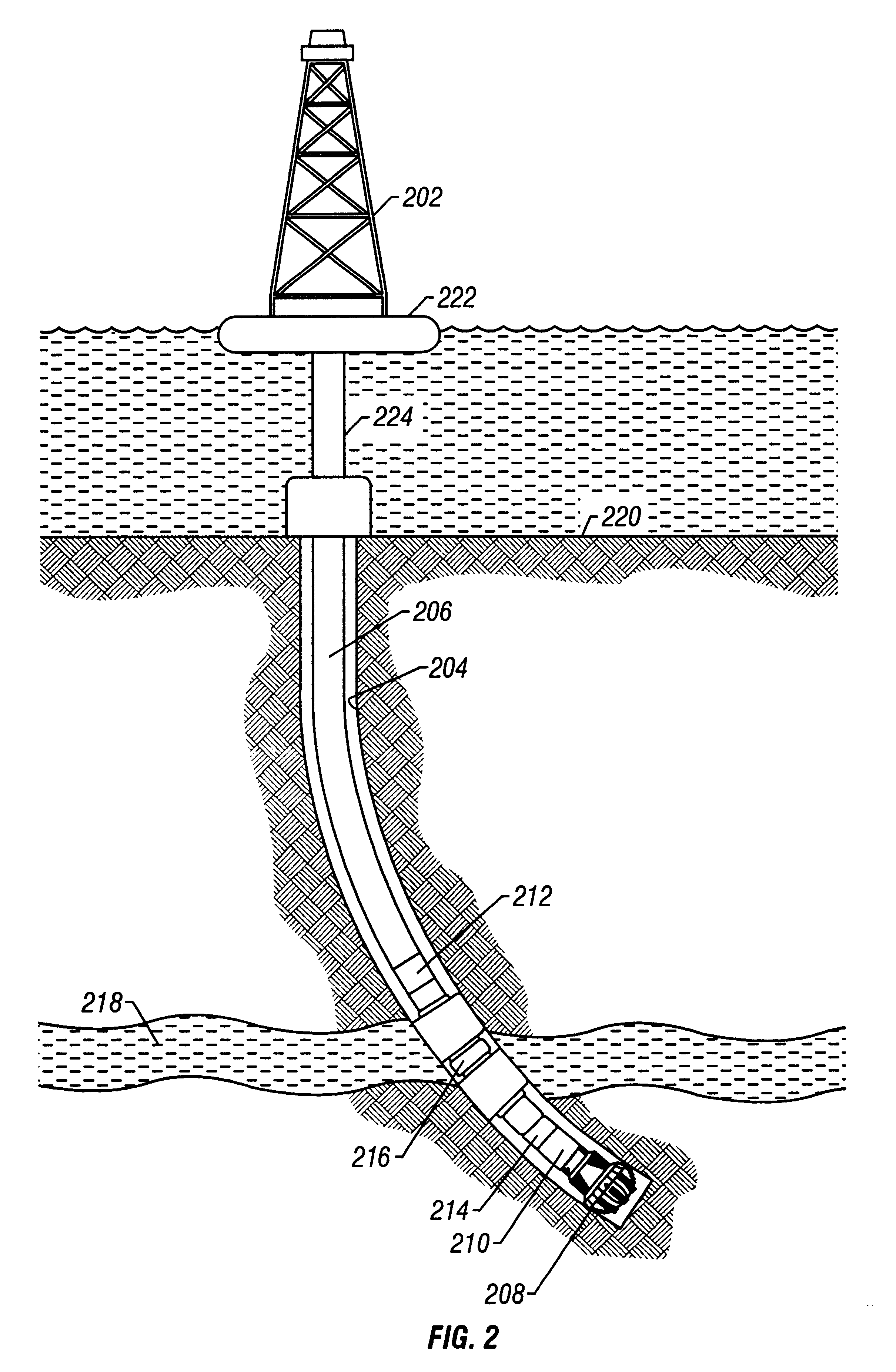
FIG. 2 is a drilling apparatus according to one embodiment of the present invention. A typical drilling rig 202 with a borehole 204 extending therefrom is illustrated, as is well understood by those of ordinary skill in the art. The drilling rig 202 has a work string 206, which in the embodiment shown is a drill string. The drill string 206 has attached thereto a drill bit 208 for drilling the borehole 204. The present invention is also useful in other types of work strings, and it is useful with a wireline, jointed tubing, coiled tubing, or other small diameter work string such as snubbing pipe. The drilling rig 202 is shown positioned on a drilling ship 222 with a riser 224 extending from the drilling ship 222 to the sea floor 220. However, any drilling rig configuration such as a land-based rig may be adapted to implement the present invention.

If applicable, the drill string 206 can have a downhole drill motor 210. Incorporated in the drill string 206 above the drill bit 208 is a...


PUM


Abstract

A method of performing a formation rate analysis from pressure and formation flow rate data. Pressure and flow rate data are measured as fluid is withdrawn from a formation. Variable system volume is accounted for. The pressure and flow rate data are correlated using a multiple linear regression technique. Time derivative terms related to pressure and flow rate are smoothed using a summation technique, thereby providing better correlations than using the time derivatives directly. Formation parameters comprising formation permeability, formation pressure, and fluid compressibility may be determined from the correlation.

Description

1. Field of the InventionThis invention relates to the testing of underground formations or reservoirs. More particularly, this invention relates to a method for determining properties of the earth formation by interpreting fluid pressure and flow rate measurements.2. Description of the Related ArtTo obtain hydrocarbons such as oil and gas, boreholes are drilled by rotating a drill bit attached at a drill string end. A large proportion of the current drilling activity involves directional drilling, i.e., drilling deviated and horizontal boreholes to increase the hydrocarbon production and / or to withdraw additional hydrocarbons from the earth's formations. Modern directional drilling systems generally employ a drill string having a bottomhole assembly (BHA) and a drill bit at an end thereof that is rotated by a drill motor (mud motor) and / or by rotating the drill string. A number of downhole devices placed in close proximity to the drill bit measure certain downhole operating paramet...

Claims


Application Information

Patent Timeline
Patent Type & Authority Patents(United States)
IPC IPC(8): E21B49/00
CPCE21B49/008
Inventor KRUEGER, SVENNIEMEYER, EICKMEISTER, MATTHIAS
Owner BAKER HUGHES HLDG LLC
Why Eureka
Try Eureka