Floating torque tube propeller shaft assembly

a propeller shaft and floating torque technology, applied in mechanical equipment, couplings, transportation and packaging, etc., can solve the problems of reducing the probability that the splines will bind under driving torque and become a source of noise or vibration, and achieve the reduction of the shaft's dynamic imbalance force, the effect of reducing the launch shudder and improving the durability life of the prop shaft assembly

Inactive Publication Date: 2009-06-09
GM GLOBAL TECH OPERATIONS LLC
View PDF13 Cites 9 Cited by
  • Summary
  • Abstract
  • Description
  • Claims
  • Application Information

AI Technical Summary

Benefits of technology

[0017]The present invention is a re-engineered propshaft assembly capable of operating at current vehicle operating speeds, and featuring: elimination of launch shudder, greatly reduced the shaft's dynamic imbalance forces, greatly improved durability life of the propshaft assembly, and reduced ability of the propshaft to transmit or amplify other vehicle generated noises such as drive axle hypoid gear noise and reducing spline friction related “clunk” or “grunt” noises.
[0019]An anti-rotation mechanism prevents rotation of the outer tube with respect to the frame of the motor vehicle. The anti-rotation mechanism prevents the outer tube from spinning from the frictional or drag forces transmitted by the spinning inner shaft through the shaft bearings. The anti-rotation mechanism can be customized to a particular application, as for example a flexible belt, cable or chain anchored to the outer tube or looped over the outer tube and anchored to the vehicle frame; a flexible mount anchoring the outer tube to the vehicle frame; a link connecting the outer tube and the vehicle frame; or a flexible boot enclosing one or both articulating joints and flexibly connecting the outer tube end(s) to the driving axle and / or the transmission. In the case of the boot, added functionality is provided by the inherent protection of the power transmitting components from the vehicle underbody environment and extending the torque tube assembly operating life by greatly slowing down corrosion related failure modes. The boot also would serve to protect the transmission rear shaft seal and the driving axle pinion seal from the external environment.
[0020]Preferred features of the torque tube propshaft assembly according to the present invention include an integral axial slip mechanism at least one end of the inner shaft and non-welded construction of the power-carrying components. The integral slip mechanism incorporates splines fabricated at the inner shaft end(s) that interface with splined yokes. One of these splined connections may be anchored with each other to force all shaft axial motion to occur at the opposite end. Aligning the longitudinal axis of the splines with the axis joining the articulating joints ensures that the axial forces generated when the distance between the shaft's attaching ends changes are aligned with the spline slip axis. This feature reduces the probability that the splines will bind under driving torque and become a source of noise or vibration during certain vehicle operations. The use of splines as the means of connecting to the end yokes eliminates the need to utilize welds to join these components in a manner generally known to be done with respect to conventional propshafts. Welding reduces component strength which is essential to transmit high driving torque with relatively small diameter shafts. This construction also allows the inner shaft to be completely disassembled to service any worn components after extended vehicle operation.
[0021]Accordingly, it is an object of the present invention to provide a propshaft assembly capable of operating at current vehicle operating speeds, and featuring: elimination of launch shudder, greatly reduced the shaft's dynamic imbalance forces, greatly improved durability life of the propshaft assembly, and reduced ability of the propshaft to transmit or amplify other vehicle generated noises such as drive axle hypoid gear noise and reducing spline friction related “clunk” or “grunt” noises.

Problems solved by technology

This feature reduces the probability that the splines will bind under driving torque and become a source of noise or vibration during certain vehicle operations.

Method used


Image

  • Floating torque tube propeller shaft assembly
  • Floating torque tube propeller shaft assembly
  • Floating torque tube propeller shaft assembly

Examples


Embodiment Construction

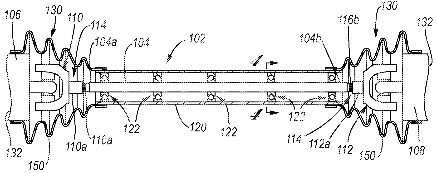
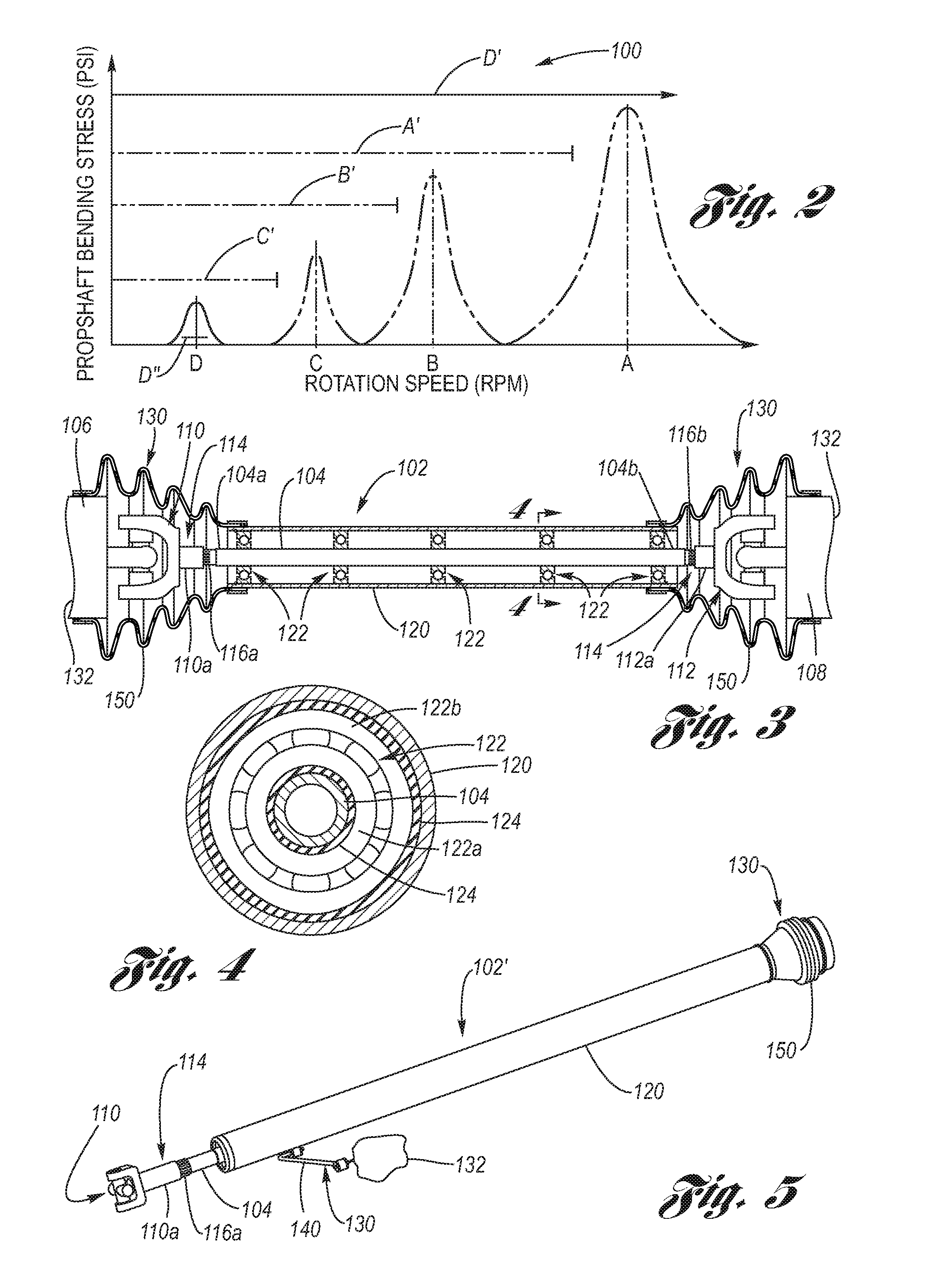
[0034]Referring now to the Drawing, FIGS. 2 through 7 depict aspects of the torque tube propshaft assembly according to the present invention.

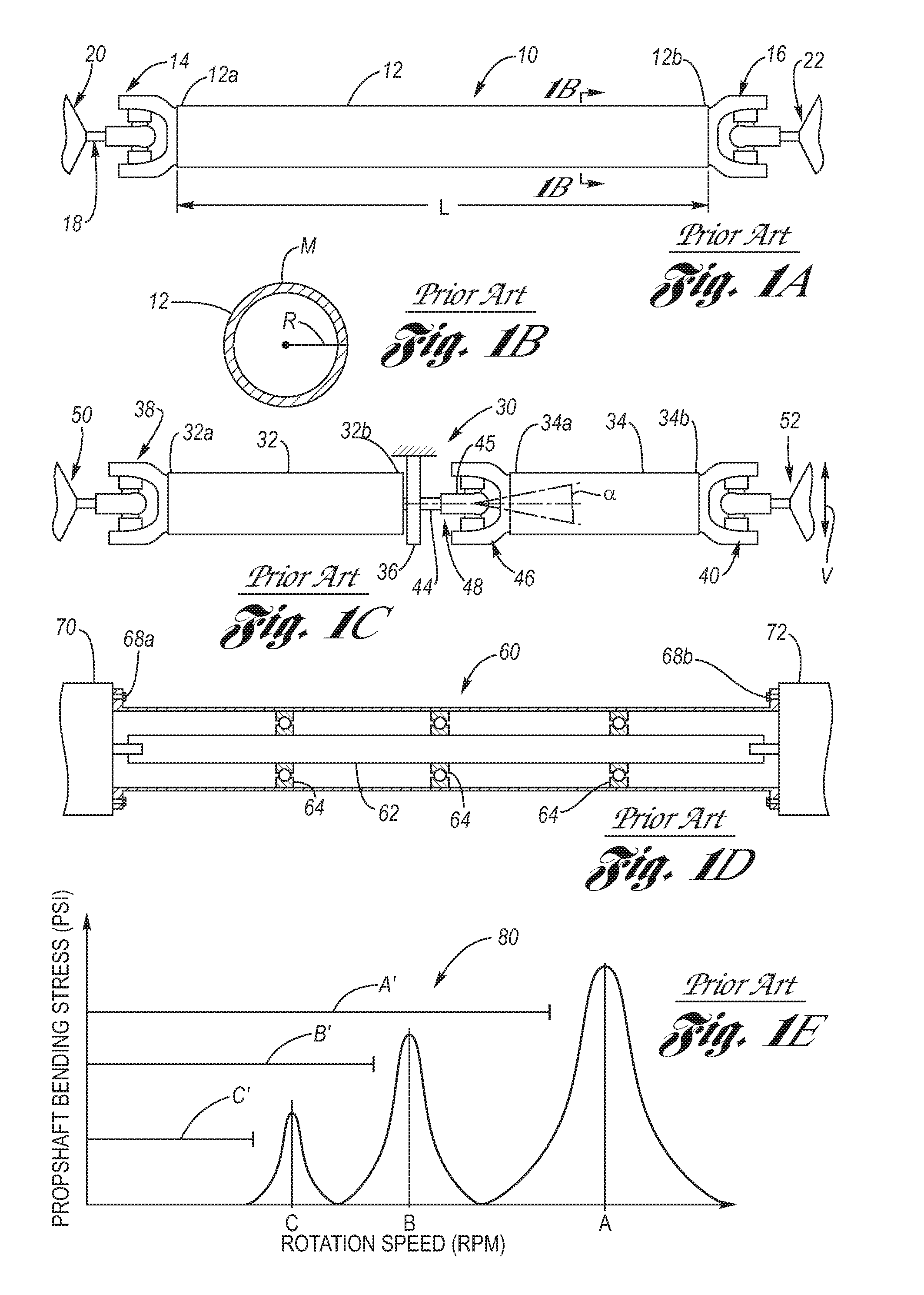
[0035]The theory of operation behind the present invention can be understood with reference to FIG. 2. Like FIG. 1E, FIG. 2 is a graphic representation 100 of the appearance of the propshaft bending stress as a function of propshaft rotation speed, wherein the propshaft critical speeds A, B, C for various designs of propshafts are now shown in phantom for comparison purposes. As is readily seen, a small diameter propshaft would have a low critical speed D, but one also sees that the bending stress at the first bending mode of vibration is much lower than the comparative values for A, B and C. Inevitably, the propshaft rotational speed within normal operational speeds of the motor vehicle will include this critical speed D, it cannot be avoided by operating the motor vehicle at propshaft rotation speeds therebelow. However, it is notable that t...


PUM


Abstract

A torque tube propshaft assembly having an outer tube free to float with movements of an inner shaft (propshaft) by being free of rigid anchorage at each end. A plurality of shaft bearings interface the outer tube with the inner shaft, wherein the outer tube is generally co-extensive with the inner shaft. An anti-rotation mechanism prevents rotation of the outer tube with respect to the frame of the motor vehicle. An axial slip mechanism is integrated with at least one end of the inner shaft. A non-welded construction of the power carrying components is provided. The outer tube provides bending support so the inner shaft does not become dynamically unstable at any rotation speed including its critical speed.

Description

TECHNICAL FIELD[0001]The present invention relates to propeller shafts used in motor vehicles for transmitting rotational torque from one component to another, as for example from a transmission to a drive axle. More particularly, the present invention relates to a reduced cross-section propeller shaft supported by bearings with respect to a floating, non-rotating outer support tube.BACKGROUND OF THE INVENTION[0002]A motor vehicle generally utilizes a propeller shaft (also referred to as a driveshaft or propshaft, and for brevity the term propshaft will be used hereinafter) to transfer the rotating mechanical force (torque) generated by the engine / transmission to the driving wheels of the vehicle, which, in turn, propel the vehicle. For example, a propshaft is used for connecting the transmission or transfer case (in the case of four or all wheel drive vehicles) to the driving axle(s). Propshafts can either be single piece, as for example shown at FIGS. 1A and 1B, or multi-piece, as...

Claims


Application Information

Patent Timeline
Patent Type & Authority Patents(United States)
IPC IPC(8): B60K17/24
CPCB60K17/22Y10T464/50F16D3/845F16F15/10
Inventor RODRIGUEZ, ROLANDO V.
Owner GM GLOBAL TECH OPERATIONS LLC
Why Eureka
Try Eureka