Vehicle fuel cap with axial longitudinal grooves in casing body

a technology of axial longitudinal grooves and fuel caps, applied in the field of fuel caps, can solve the problems of surface treatment film loss, difficult to discharge (earth) static, and rus

Active Publication Date: 2009-06-09
HONDA MOTOR CO LTD +1
View PDF6 Cites 6 Cited by
  • Summary
  • Abstract
  • Description
  • Claims
  • Application Information

AI Technical Summary

Benefits of technology

[0015]In accordance with the vehicle fuel cap of the first aspect of the present invention, because the discharge portion comprises the projection form provided on the inner peripheral face of the lid, it can narrow a gap between the inner peripheral face of the lid and the filler neck, prevent a dust from invading into the fuel cap from the gap, and thus make an outer diameter of the lid smaller.
[0016]In addition, the lid can improve a dust prevention and an appearance thereof with keeping a dimensional accuracy by changing a slit formed in a lid of a conventional fuel cap to a longitudinal groove.
[0017]Furthermore, on the inner peripheral face of the lid is formed the longitudinal groove along the axial direction of the casing body. The longitudinal groove can prevent an occurrence of a surface sink due to a thermal contraction, where the inner peripheral face of the lid becomes a depression, and improve a dimensional accuracy of a gap between the discharge portion and the filler neck in injection-molding the lid with a conductive resin material and cooling / solidifying it. Thus when a fuel filling person attaches / detaches a fuel cap, static charged in him / her is preferably discharged, and thereby a discomfort by the static can be eliminated.
[0019]In accordance with the vehicle fuel cap of the second aspect of the present invention, even when because the depression is formed at the opening end side of the longitudinal groove of the lid, an end of the lid screwed in a filler neck abuts with a vehicle body due to a dimensional variation, a passage communicating in an atmospheric air from relief valves (positive pressure valve and negative pressure valve) for adjusting an air pressure within a fuel tank can be prevented by the depression from being shut off.

Problems solved by technology

When the gap L1 is too large, it becomes difficult to discharge (earth) static.
In addition, in this case the lid 200 and the filler neck 300 make contact and wear, thereby a surface treatment film is lost, and a rust also sometimes occurs.

Method used


Image

  • Vehicle fuel cap with axial longitudinal grooves in casing body
  • Vehicle fuel cap with axial longitudinal grooves in casing body
  • Vehicle fuel cap with axial longitudinal grooves in casing body

Examples


Embodiment Construction

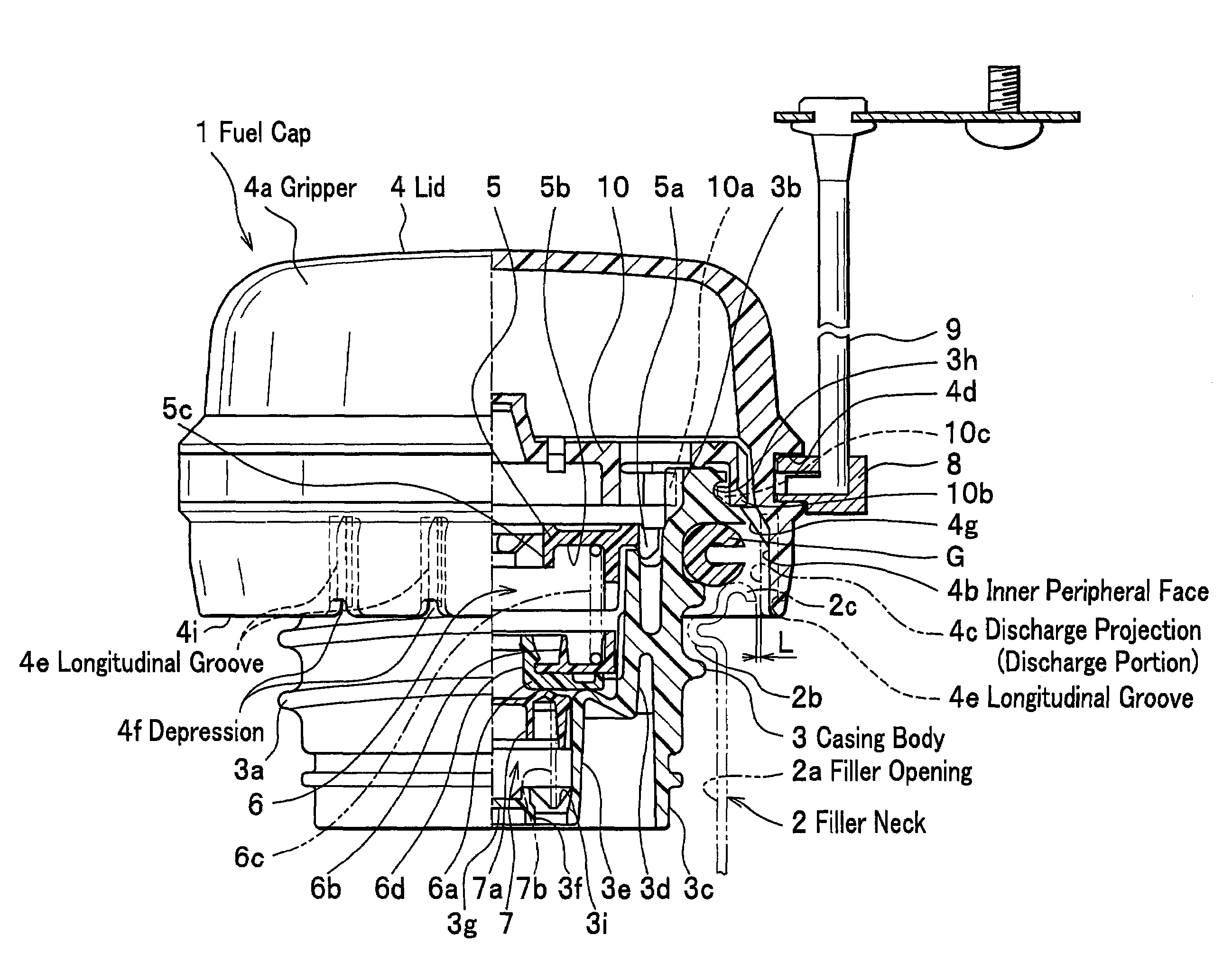
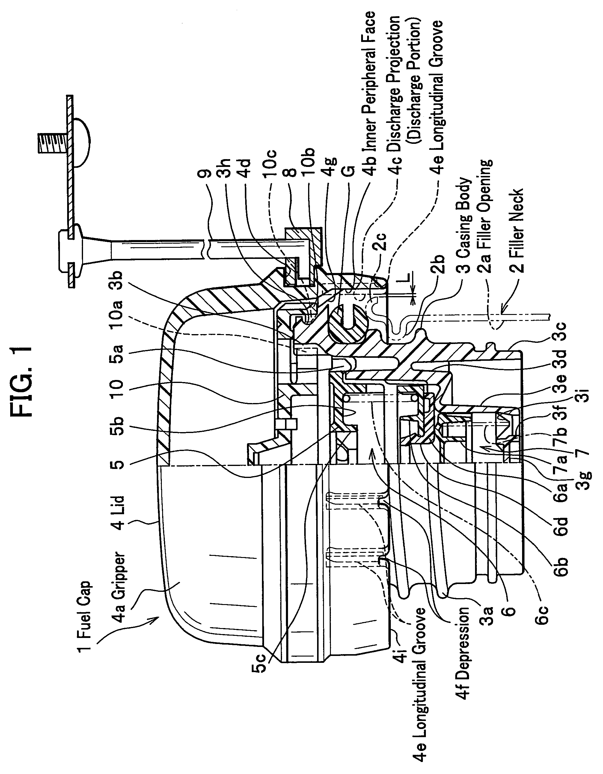
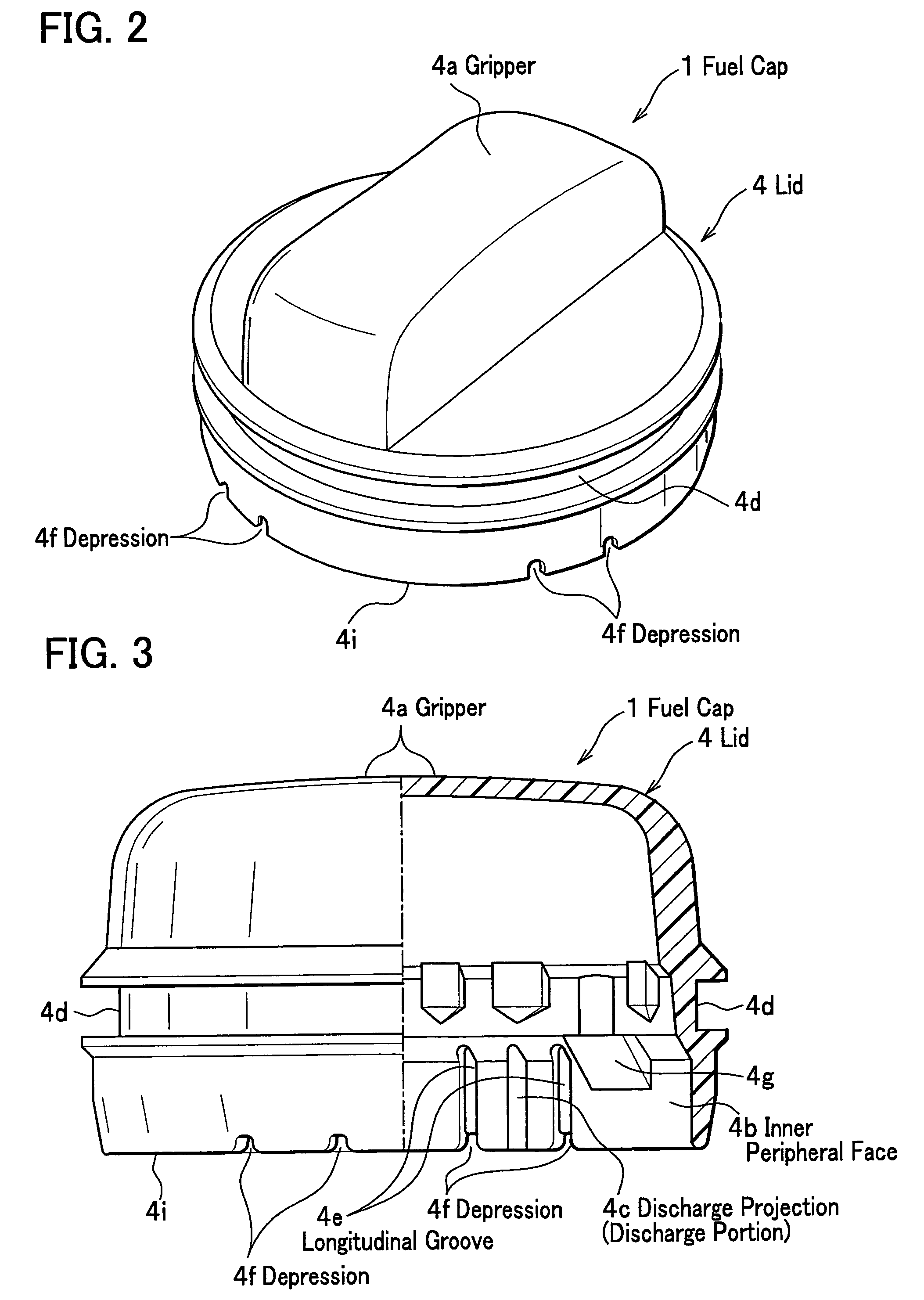
[0026]Here will be described a vehicle fuel cap of an embodiment of the present invention, referring to FIGS. 1 to 5.

[0027]FIG. 1 is a half-section drawing showing a vehicle fuel cap related to an embodiment of the present invention.

[0028]Meanwhile, although because a fuel cap 1 changes in an up / down direction according to a placement direction thereof, its direction is arbitrary, hereinafter a description will be performed, making it an up direction a direction where a lid 4 of FIG. 1 is arranged.

[Fuel Cap]

[0029]As shown in FIG. 1, the fuel cap 1 is a lid member screwed in a filler neck 2, where a filler opening 2a for supplying fuel to a fuel tank (not shown) is formed, and for opening / closing the filler opening 2a. The fuel cap 1 comprises a casing body 3 screwed in the filler neck 2; the lid 4 that is equipped at an upper portion of the casing body 3 through a torque plate 10 and has a gripper 4a which a fuel filling person pinches with fingers; an inside lid 5 for closing an up...


PUM

PropertyMeasurementUnit
volume specific resistivityaaaaaaaaaa
discharge distanceaaaaaaaaaa
conductiveaaaaaaaaaa

Abstract

A vehicle fuel cap comprises a casing body for opening / closing a filler opening of a filler neck communicating with a fuel tank; and a lid that is equipped at an upper portion of the casing body and is formed of a conductive material, and the vehicle fuel cap forms a discharge portion in the lid for discharging static charge in the lid to the filler neck, wherein the discharge portion comprises a projection form provided on an inner peripheral face of the lid opposite to an outer peripheral edge of the filler opening, and on the inner peripheral face a longitudinal groove is formed at both sides of the discharge portion and along an axial direction of the casing body.

Description

BACKGROUND OF THE INVENTION[0001]1. Field of the Invention[0002]The present invention relates to a fuel cap for opening / closing a filler opening of a fuel tank of a vehicle, and particularly, to a vehicle fuel cap where static charge in a human body is earthed through the fuel cap.[0003]2. Description of the Related Art[0004]Conventionally, a vehicle fuel cap is known as disclosed in paragraphs 0052 to 0063 and FIGS. 1, 11, 16 32, and 33 of Japanese Patent No. 3389850 (hereinafter referred to as patent document 1).[0005]FIGS. 6A and 6B are drawings showing a conventional vehicle fuel cap: FIG. 6A is a perspective drawing of a lid of the fuel cap; FIG. 6B is a half-section drawing of the fuel cap.[0006]As shown in FIG. 6B, a conventional vehicle fuel cap 100 is designed to form a lid 200 having a gripper 210, which a fuel filling person grips, of a conductive resin member, to make a discharge projection 220 of the lid 200 come near a filler neck 300 made of steel, and thereby to disc...

Claims


Application Information

Patent Timeline
Patent Type & Authority Patents(United States)
IPC IPC(8): B65D51/16B60C19/08B65D53/00
CPCB60K15/0406B60K2015/03401Y10S220/33
Inventor HOKAZONO, SHOICHITERADA, YOSHINOBUISHIDA, KAZUHISA
Owner HONDA MOTOR CO LTD
Why Eureka
Try Eureka