Gas chromatograph with a mass spectrometer situated down therefrom, and method for performing the gas chromatographic/mass spectrometric analysis of a substance mixture

a gas chromatograph and mass spectrometer technology, which is applied in the direction of particle separator tube details, instruments, separation processes, etc., can solve the problems of undesired presence of carrier gas which comes out of the gas chromatograph together with the separated materials, and achieves the effect of minimal amount of carrier gas entering the mass spectrometer, cheaper and more powerful

Inactive Publication Date: 2009-06-09
SIEMENS AG
View PDF15 Cites 1 Cited by
  • Summary
  • Abstract
  • Description
  • Claims
  • Application Information

AI Technical Summary

Benefits of technology

[0003]For gas chromatographic analysis of a substance mixture this mixture is directed together with a carrier gas through a chromatographic separation device in which the substances of the substance mixture are separated as a result of their different retention times and thus appear one after the other at the output of the separation device. Different detectors, such as heat conductivity detectors or flame ionization detectors for example, are available for the detection of the separated materials. The use of a mass spectrometer as detector also makes it possible, in addition to detecting the chromatographically separated materials, to differentiate between materials with the same retention times but different masses. Since the mass spectrometric analysis of materials is undertaken in a vacuum, the presence of the carrier gas which comes out of the gas chromatograph together with the separated materials is undesired. The mass spectrometer is thus connected via a controllable inlet valve to the output of the separation device, said inlet valve only being opened on demand, that is on arrival of the separated materials, with the carrier gas being removed as well (DE 1598568). Although it is possible to detect in the removed carrier gas the arrival of the separated substance mixture and to open the inlet valve as a function of this event, a part of the separated material, namely that material removed at the start with the carrier gas, is lost to mass spectrometric analysis in this case. The control of the feeding of separated materials to the mass spectrometer can thus only be undertaken in a relatively crude manner by adhering to safety times, so that a not insignificant amount of carrier gas gets into the mass spectrometer and a correspondingly high pump power is required to generate the necessary vacuum.
[0007]The separated materials appearing at the output of the separation device are detected in-line and non-destructively, with only those materials being forwarded to the mass spectrometer which have been selected for a further mass spectrometric analysis. As a result of the speed of the carrier gas stream the time taken by the materials to pass from the detector to the inlet valve of the mass spectrometer is known, so that the materials can be transferred very selectively to the mass spectrometer and thus the amount of carrier gas entering the mass spectrometer is minimal. The pump power for creation of the vacuum in the mass spectrometer can thus be correspondingly small, so that very small pumps, e.g. ion getter pumps, can be employed. This produces benefits as regards costs, service life, maintenance requirements and power consumption. Further the scope of measurement signal evaluation in the mass spectrometer is restricted just to the materials fed selectively to it, so that its electronics and software can be designed to be cheaper and more powerful (fast).

Problems solved by technology

Since the mass spectrometric analysis of materials is undertaken in a vacuum, the presence of the carrier gas which comes out of the gas chromatograph together with the separated materials is undesired.

Method used


Image

  • Gas chromatograph with a mass spectrometer situated down therefrom, and method for performing the gas chromatographic/mass spectrometric analysis of a substance mixture
  • Gas chromatograph with a mass spectrometer situated down therefrom, and method for performing the gas chromatographic/mass spectrometric analysis of a substance mixture

Examples


Embodiment Construction

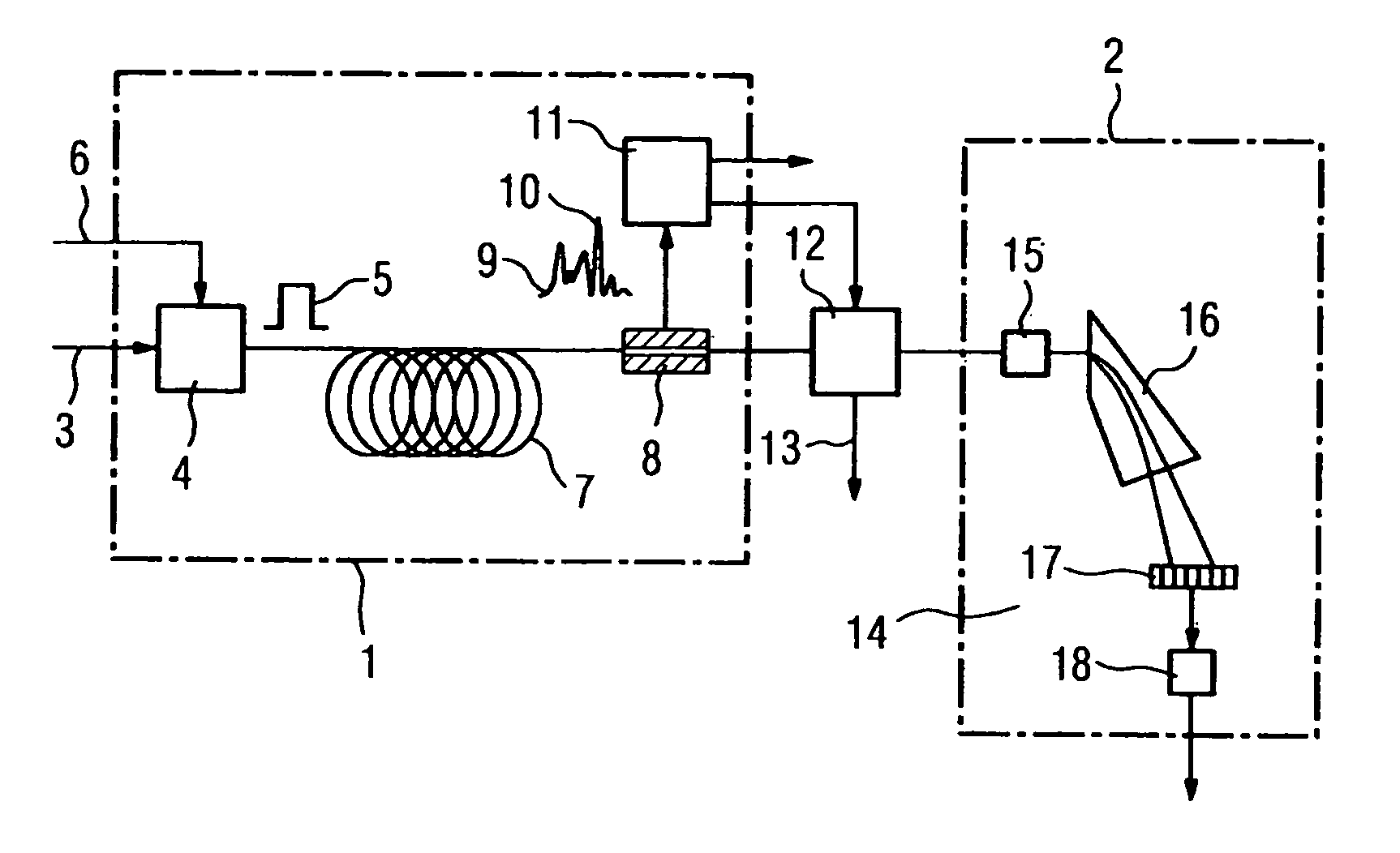
[0014]FIG. 1 shows a gas chromatograph 1 with a downstream mass spectrometer 2 for analysis of a substance mixture (sample) 3, which is fed, after being taken out of a technical process and prepared, to a dosing device 4. The dosing device 4 is used to feed at a predetermined point in time a predetermined dosing amount of the sample 3 in the form of a short and precisely limited sample drop 5 into a carrier gas stream 6 and feed it to a separation device 7 in the form of a separation column or separation column circuit. The separation device 7 separates the materials contained in the sample drop 5 in accordance with their retention periods, so that the materials appear at the output of the separation device 7 in turn.

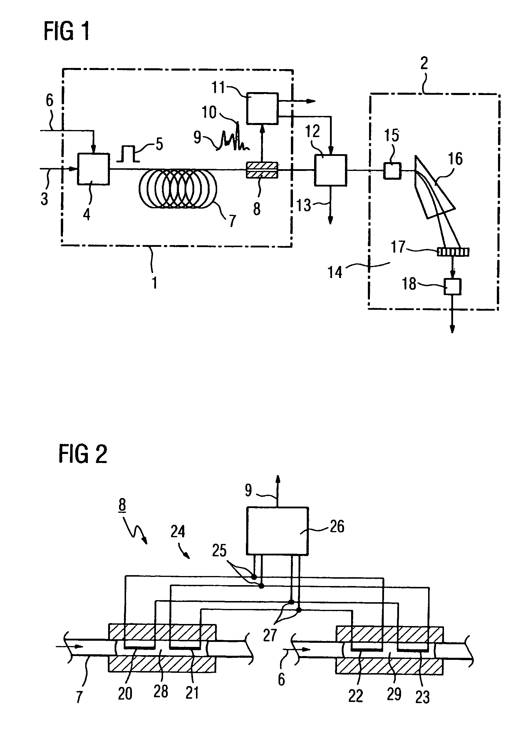
[0015]A detector 8 for detecting the separated materials is arranged at the output of the separation device 7. The detector 8 delivers a detector signal 9 which contains a peak 10 for each separated material, the surface of said peak being proportional to the amount of ...


PUM

PropertyMeasurementUnit
dimensionsaaaaaaaaaa
heat conductivityaaaaaaaaaa
gas chromatographaaaaaaaaaa

Abstract

The aim of the invention is to optimize the analysis of substances separated by gas chromatography with a gas chromatograph, comprising a separating device and a mass spectrometer situated down there from. To this end, a detector that detects the separated substances in a nondestructive manner is placed in-line between the output of the separating device and a controllable inlet valve of the mass spectrometer. An evaluating device situated down from the detector evaluates the detector signals and, based on the evaluation, controls the inlet valve for introducing predeterminable substances into the mass spectrometer.

Description

CROSS REFERENCE TO RELATED APPLICATIONS[0001]This application is the US National Stage of International Application No. PCT / EP2004 / 004483, filed Apr. 28, 2004 and claims the benefit thereof. The International Application claims the benefits of German application No. 10319130.5, filed Apr. 28, 2003, both applications are incorporated by reference herein in their entirety.FIELD OF INVENTION[0002]The invention relates to a gas chromatograph with downstream mass spectrometer and a method for gas chromatographic mass spectrometric analysis of a substance mixture.SUMMARY OF THE INVENTION[0003]For gas chromatographic analysis of a substance mixture this mixture is directed together with a carrier gas through a chromatographic separation device in which the substances of the substance mixture are separated as a result of their different retention times and thus appear one after the other at the output of the separation device. Different detectors, such as heat conductivity detectors or flam...

Claims


Application Information

Patent Timeline
Patent Type & Authority Patents(United States)
IPC IPC(8): B01D53/02G01N30/02G01N30/72G01N30/78H01J49/04
CPCG01N30/78H01J49/0422G01N30/7206G01N2030/025G01N30/66
Inventor DIEDRICH, FRANKMULLER, FRIEDHELM
Owner SIEMENS AG
Why Eureka
Try Eureka