
Load control unit in communication with a fixed network meter reading system

a technology of load control and reading system, applied in adaptive control, analysing/displaying, instruments, etc., can solve problems such as loss of transmission capability, loss of generation, and curtailing or interrupting load at a customer location, and achieve the effect of reducing latency

Active Publication Date: 2009-06-09
ELSTER ELECTRICTY LLC
View PDF345 Cites 57 Cited by
  • Summary
  • Abstract
  • Description
  • Claims
  • Application Information

AI Technical Summary

Benefits of technology

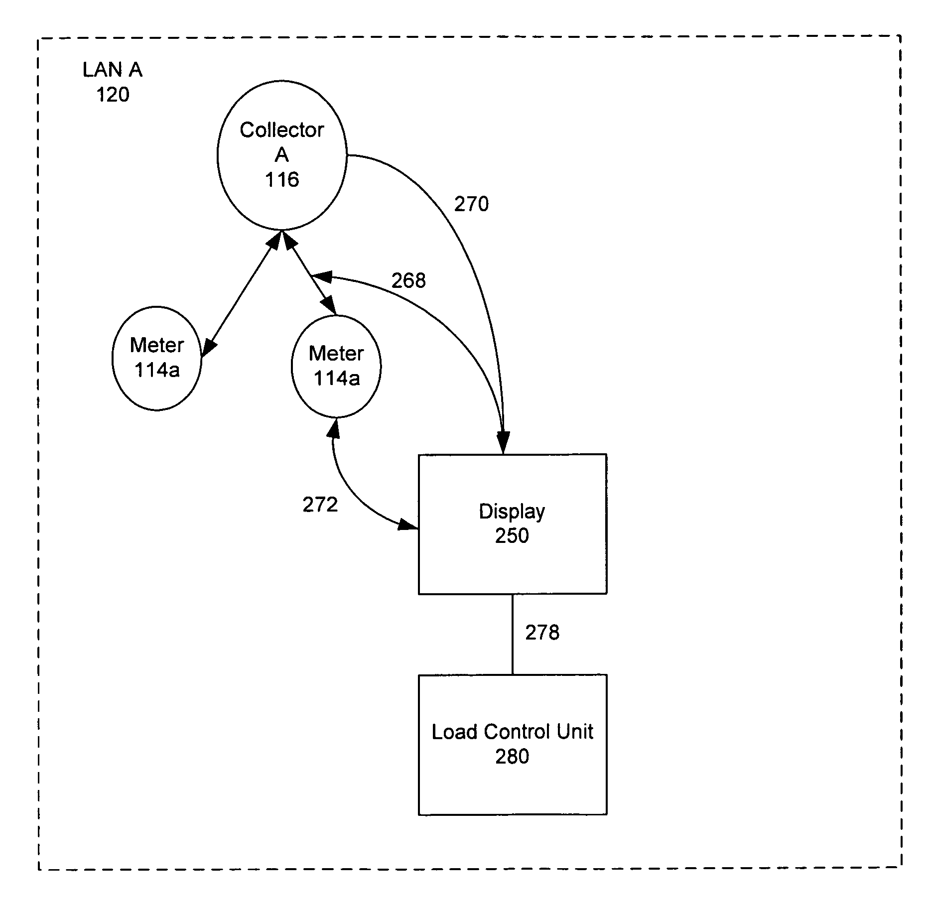
"The invention is a system and method for controlling loads in a power distribution system. It uses existing communication systems to interrupt and shed loads at a customer location. The system includes a master controller that receives information about the customer's usage and sends instructions to a load control unit to interrupt certain loads. The system can also be used for load shedding, where the master controller sends a command to disconnect loads based on certain action levels. The command is sent via a TCP / IP communication system and a radio network to reduce latency. The system can also predict which loads will be needed and shed them in advance. Overall, the invention allows for more efficient and effective load control in power distribution systems."

Problems solved by technology

Loads at a customer location may be curtailed or interrupted during power system events for several reasons.
Abnormal conditions include events such as loss of transmission capability due to a line outage, loss of generation, loss of inter-tie to adjacent power networks, unusually high peak demand or similar type events.
One drawback of such systems is that they require additional equipment at a customer premises and additional systems to manage the equipment.

Method used


Image

  • Load control unit in communication with a fixed network meter reading system
  • Load control unit in communication with a fixed network meter reading system
  • Load control unit in communication with a fixed network meter reading system

Examples


Embodiment Construction

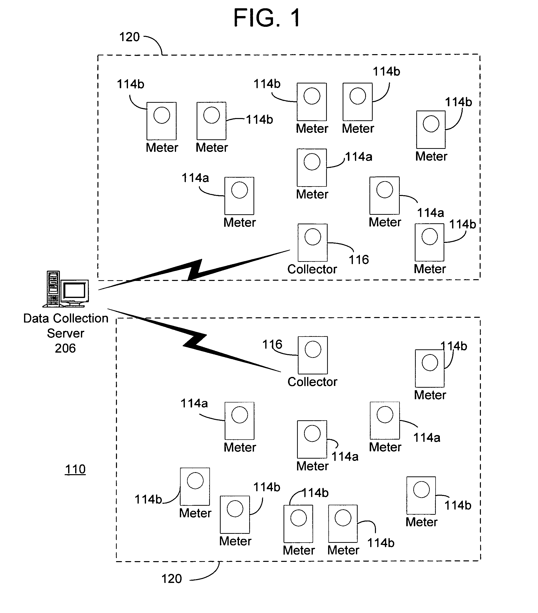
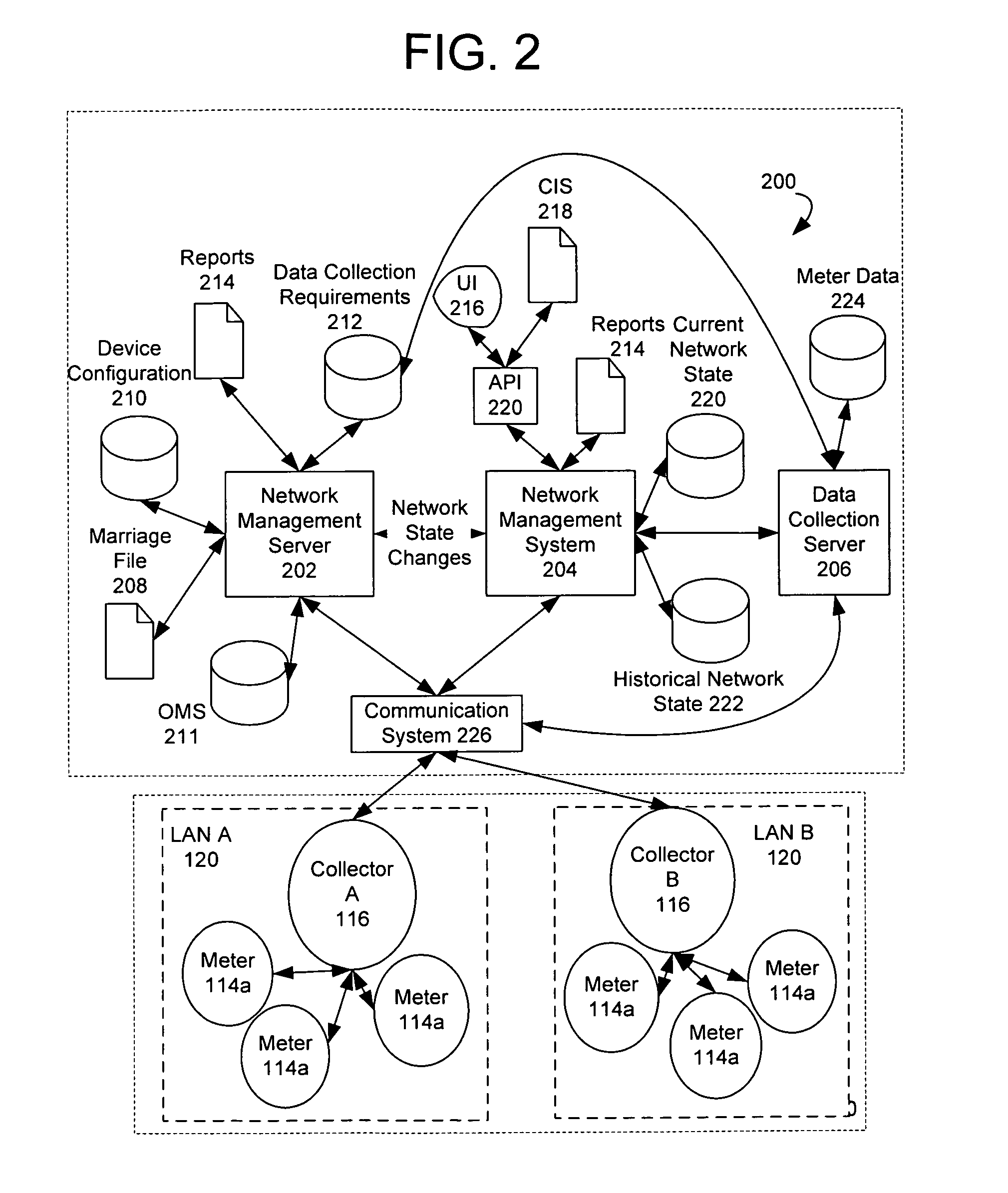
[0011]Exemplary systems and methods for gathering meter data are described below with reference to FIGS. 1-2. It will be appreciated by those of ordinary skill in the art that the description given herein with respect to those figures is for exemplary purposes only and is not intended in any way to limit the scope of potential embodiments.

[0012]Generally, a plurality of meter devices, which operate to track usage of a service or commodity such as, for example, electricity, water and gas, may be operable to wirelessly communicate with each other and / or to communicate with one another via a wireline network. A collector may be operable to automatically identify and register meters for communication with the collector. When a meter is installed, the meter becomes registered with the collector that can provide a communication path to the meter. The collectors may receive and compile metering data from a plurality of meter devices via wireless communications. Also, a communications serve...


PUM


Abstract

A load control system that communicates with existing automated meter reading communications systems to interrupt and shed loads at a customer location. The system includes a master controller that listens to communications between a utility meter and the reading system. The controller receives tier and / or pricing information and will instruct a load control unit to interrupt certain loads based on the information. In addition, the system may be employed as a load shedding system where a command may be forwarded to the master controller to disconnect loads based on action levels. The command may be sent via a TCP / IP communications system to a node in the reading system and the forwarded via a radio network to the master controller to reduce latency. Predictive shedding may be performed based on forecast loads.

Description

FIELD OF THE INVENTION[0001]The present invention relates to an energy management system, and more particularly, to systems and methods for controlling or shedding loads at a customer location via a fixed network meter reading system.BACKGROUND OF THE INVENTION[0002]Loads at a customer location may be curtailed or interrupted during power system events for several reasons. Depending on the driver, the load reduction may be initiated by the utility or by the customer. For the customer, load reduction is generally an attempt to decrease energy consumption during certain periods of time to reduce costs. Predetermined loads such as HVAC, hot water heaters, pool pumps, or other high consumption devices can be selected for energy interruption to reduce the overall consumption when higher energy prices are in effect.[0003]For the utility, load shedding at a customer site may be accomplished because of an abnormal condition on the power network. Abnormal conditions include events such as lo...

Claims


Application Information

Patent Timeline
Patent Type & Authority Patents(United States)
IPC IPC(8): G08C19/16
CPCG01D4/004Y02B90/242Y02B90/244Y02B90/246Y04S20/322Y04S20/327Y04S20/42Y02B90/20Y04S20/30G01D2204/12G01D2204/45
Inventor SHUEY, KENNETH C.BORLESKE, ANDREW J.MASON, JR., ROBERT T.HART, DAVID G.
Owner ELSTER ELECTRICTY LLC
Learn More