Laser projection systems and methods

a laser and surface technology, applied in the field of laser projection systems and methods, can solve the problems of cumbersome use of reference laser targets, limited applications of laser projection systems, and difficult accurate projection

Active Publication Date: 2009-06-09
NIKON METROLOGY
View PDF12 Cites 79 Cited by
  • Summary
  • Abstract
  • Description
  • Claims
  • Application Information

AI Technical Summary

Benefits of technology

[0009]The method of this invention then includes generating a signal from the external metrology device to a computer and the computer then uses the data received from the metrology device to determine the position and orientation of the laser projector relative to the target surface. The metrology receivers may be connected to the computer or the data from the metrology receivers may be transmitted to the computer by a wireless system. The method of this invention then includes orienting a laser from the laser projector or projectors relative to the target surface to a project laser template on the target surface at a predetermined or defined location and orientation using the data from the computer and finally projecting the laser template on the target surface at the predetermined location and orientation with the laser projector. The method of projecting a laser template on a target surface of this invention thus eliminates the requirement for laser targets on or adjacent the target surface and calibration of the laser projector relative to laser targets on or adjacent the target surface and is thus “targetless.” Further, the metrology receivers do not have to be within a field of view of the laser projector or projectors.
[0011]In one preferred embodiment of the frame assembly of this invention disclosed herein, the frame includes a support surface and a distal open end. The laser projector is rigidly supported on the support surface of the frame assembly and the method of this invention then includes projecting the laser template through the distal open end of the frame assembly. The metrology receivers in the disclosed embodiment of the frame assembly are attached at predetermined locations to the distal open end of the frame assembly for accurately determining the position and orientation of the laser targets and thus the laser projector by the method of this invention. Further, in the disclosed embodiment of the frame assembly, the laser targets are also located on the distal open end of the frame assembly opposite the laser projector. The method of this invention then includes periodically scanning the laser targets on the distal open end of the frame assembly and correcting for laser image drift or movement of the laser projector. However, where the metrology receivers are fixed relative to the laser targets, the laser projector may move relative to the frame and determine its position and orientation by scanning the laser targets. As used herein, the term “periodically” includes continuously scanning the laser targets and the laser targets may be retroreflective targets or any suitable laser target or position sensor, as disclosed for example in the above referenced U.S. Pat. No. 5,646,859.
[0014]As set forth above, the laser projection system and method of this invention is particularly, but not exclusively suitable for projecting a laser template on a target surface, where laser targets would interfere with subsequent operations, such as ply layup on large target surfaces, such as an aircraft body, for subsequent operations, such as the application of decals, placement of fixtures and covering the joints between the components of the target surface, such as an aircraft. Of course, however, the laser projection system and method of this invention is not limited to any particular application. In such applications, however, it is desirable to fix the metrology receivers or reflectors on stanchions, such that the reflector or receiver is located above the floor for ease of reference in determining the position and orientation of the target surface. In one preferred embodiment of the metrology receiver assembly of this invention, the receiver assembly may be removed from the support and replaced without changing the position and orientation of the metrology receiver. In this embodiment, the metrology receiver assembly includes a support stanchion adapted to be permanently affixed to a support in a workstation in a predetermined location. A bottom kinematic plate is fixed to the top of the support stanchion and the assembly includes a receiver support member having a top kinematic plate secured to the support member releasably attached to the bottom kinematic plate. In a preferred embodiment of the receiver assembly, one of the top and bottom kinematic plates includes a plurality of spaced projecting portions and the other of the top and bottom kinematic plates has a plurality of spaced recesses configured to receive the spaced projecting portions to align and orient the top kinematic plate relative to the bottom kinematic plate, such that the top kinematic plate, receiver support and metrology receiver or reflector may be removed from and replaced on the support stanchion without changing the position and orientation of the metrology receiver. In the disclosed embodiment of the metrology receiver assembly of this invention, the top kinematic plate is releasably attached to the bottom kinematic plate by a magnet, such that the top kinematic plate, receiver support and metrology receiver may be easily removed from and replaced on the support stanchion without changing the position and orientation of the assembly.

Problems solved by technology

However, as set forth above, the requirement for laser targets at fixed locations on or adjacent the target surface has limited the applications for laser projection systems.
Further, if the structure or target surface is very large, the required laser projection area may be too large to allow placement of laser or reference targets within the field of view of the laser projectors, making accurate projection difficult.
Further, the use of reference laser targets is cumbersome, initially requiring mounting of appropriate laser target locations on the target or tool together with accurate measurement of each target coordinate, typically using a theodelite laser tracker or other coordinate measuring machine (CMM).

Method used


Image

  • Laser projection systems and methods
  • Laser projection systems and methods
  • Laser projection systems and methods

Examples


Embodiment Construction

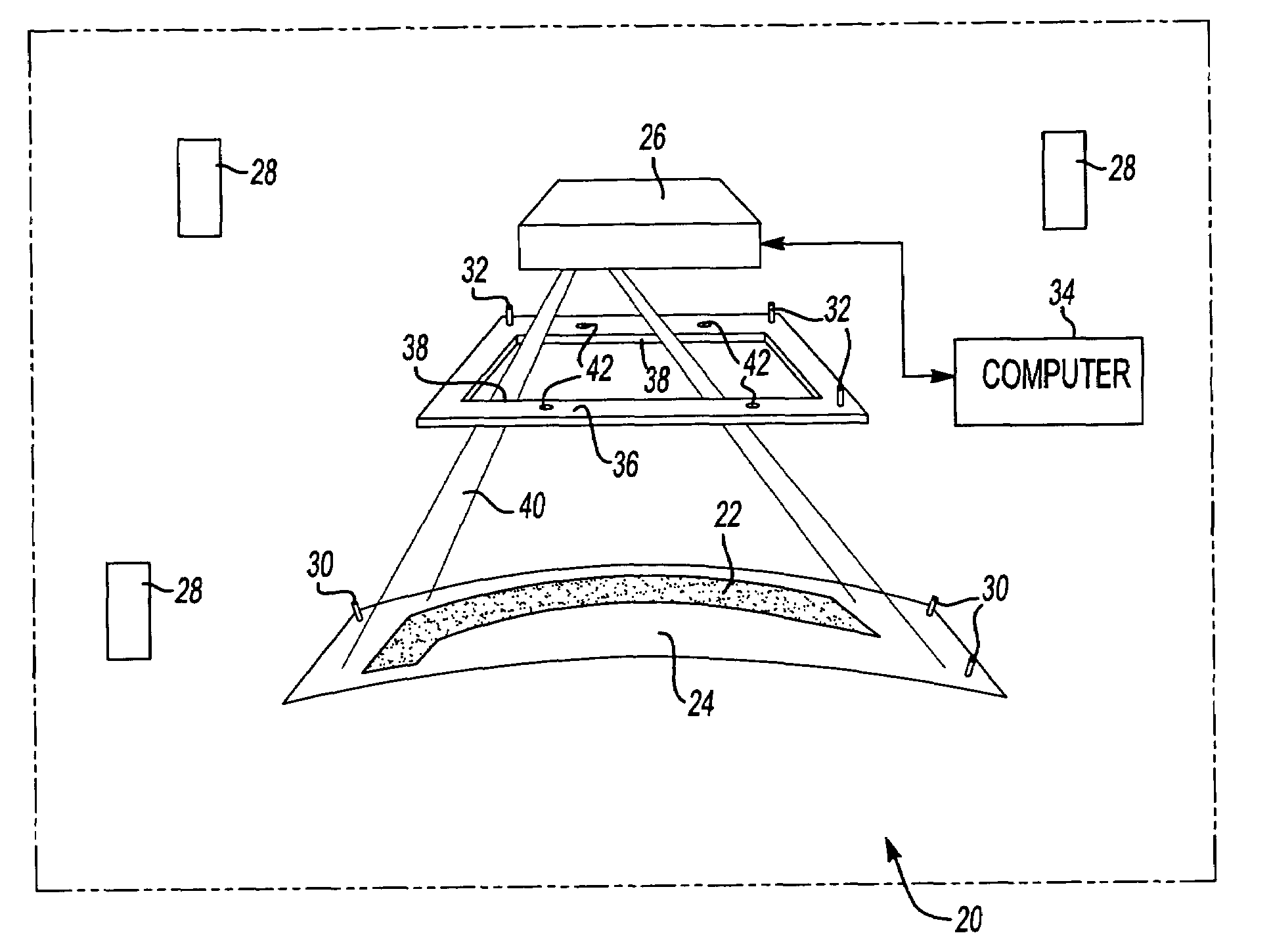
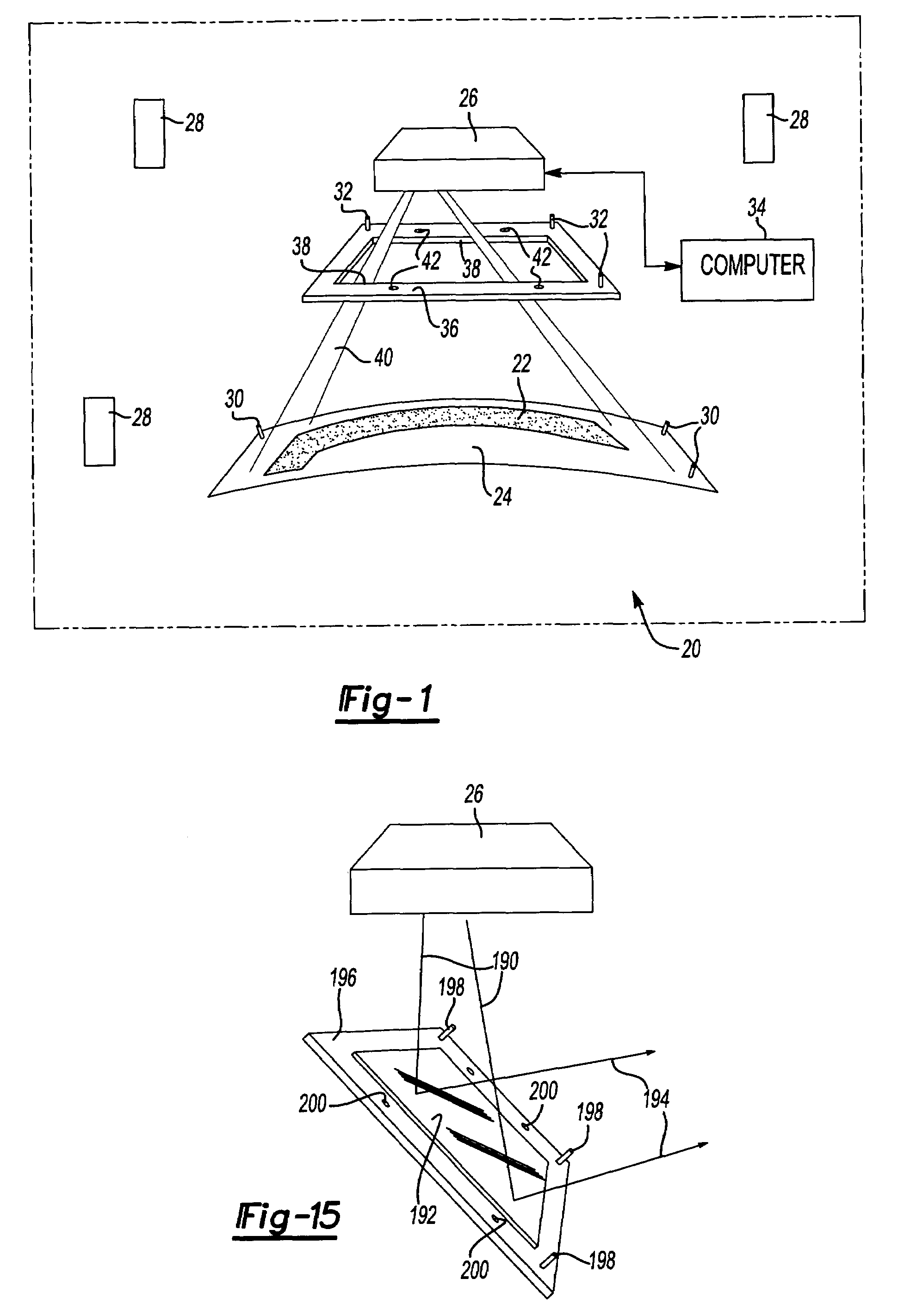
[0034]FIG. 1 illustrates schematically one embodiment of a targetless laser projection system 20 and method of this invention for projecting a laser template 22 on a target surface 24 with a laser projector 26. The laser projector 26 may be any conventional laser projector, such as the LPS1 laser projector available from the assignee of this application. The disclosed embodiment of the targetless laser projection system 20 shown in FIG. 1 includes a plurality of metrology transmitters 28 at fixed locations preferably within the work area, such as the indoor GPS infrared light metrology transmitters available from Arc Second, Inc. of Dulles, Va. or the laser trackers described above. Alternatively, other transmitter metrology devices may be utilized, as described above, including but not limited to, laser theodelite transmitter tracking devices, optical photogrametery devices, camera based systems, other infrared transmitter metrology devices and other tracker projection devices. The...


PUM

PropertyMeasurementUnit
projection angleaaaaaaaaaa
flexibilityaaaaaaaaaa
temperatureaaaaaaaaaa

Abstract

A laser imaging system and method of projecting a laser template on a surface, including independently determining a position and orientation of the surface using an external metrology device, independently determining a position and orientation of a laser projector using the metrology device, generating a signal from the metrology device to a computer and orienting the laser projector relative to the surface to project a laser template. The apparatus includes a plurality of metrology transmitters at fixed locations, a plurality of metrology receivers at fixed locations relative to the surface and a plurality of metrology receivers at fixed locations relative to either the laser projector or laser targets within a field of view of the laser projector. A laser projector and frame assembly is also disclosed, wherein the metrology receivers are located on the frame and the frame includes laser targets for correcting laser drift. Kinematic supports for the metrology receivers are disclosed as well as an independent laser tracker.

Description

RELATED APPLICATIONS[0001]This application claims priority to U.S. Provisional Patent Application Ser. No. 60 / 501,885, filed Sep. 10, 2003.FIELD OF THE INVENTION[0002]This invention relates to a method and apparatus for projecting a laser template on a surface particularly including a method and apparatus for projecting a laser template on a surface without laser targets on the surface, or a “targetless” laser projection system and method which increases the application of laser projection systems, including projection of laser templates on larger surfaces, such as aircraft, or where laser targets on the surface would interfere with further operations or conventional laser projection systems would be impractical or impossible.BACKGROUND OF THE INVENTION[0003]Visible laser projection systems are now widely used in industry to project a laser outline or “template” on a work or target surface for assembling large two or three-dimensional structures or assemblies, such as prefabricated ...

Claims


Application Information

Patent Timeline
Patent Type & Authority Patents(United States)
IPC IPC(8): G01B11/14B23K26/00B25H7/00F41G3/26G01S5/16G03B21/00G06F19/00H04N
CPCB25H7/00G01S5/16G01S5/163
Inventor RUEB, KURT D.JACKSON, V. ROBERTMORDEN, JARRAD V.
Owner NIKON METROLOGY
Why Eureka
Try Eureka