Shallow angle shape sensor

a sensor and angle angle technology, applied in the field of shape determination, can solve the problems of low sensitivity of the measurement to the quantity of interest, introduce additional complexity, and scan system introduce performance limitations, and achieve the effects of low sensitivity, high resolution and large area

Active Publication Date: 2009-06-16
LOCKHEED MARTIN CORP
View PDF8 Cites 15 Cited by
  • Summary
  • Abstract
  • Description
  • Claims
  • Application Information

AI Technical Summary

Benefits of technology

[0015]The sensor devices are mounted to a common base such as, for example, a spacecraft bus in space applications, with their lines-of-sight at a shallow angle to the plane of the surface. One or more sensor devices may be used to cover the entire surface or to provide enough coverage to allow shape determination. The sensor devices are mounted close to each other so their relative motion can be neglected and their measurements easily reconciled to provide deflection information over the entire surface. This leads to simple calibration and higher stability of the imaging system.
[0016]The present invention provides a number of advantages and benefits and addresses various limitations inherent to other methods and approaches that have been proposed for shape determination of large space-, air- and ground-based systems. For example, in one implementation, the SASS system is mounted close to the surface of a structure for which the shape is to be determined and, hence, does not require the deep back / front structure needed by range-based metrology systems and stereo video systems. The SASS system also does not suffer from the sensitivity limitations of range-based metrology and stereo video systems for points far away from the sensors or metrology launchers. This is due to the unique SASS design. The sensors' lines-of-sight at a shallow angle to the surface provide measurements that are very sensitive to deflections normal to the plane of the surface over the entire surface area covered by the sensors.
[0018]The SASS system is expected to be low cost, reliable and have high performance. Using existing Charged Coupled Device (CCD) camera technology, SASS systems can be designed for surfaces of hundreds of meters and achieve accuracy of 0.1-mm and bandwidth of several Hertz. With this performance, it should meet the requirements for critical applications such as extremely large space-based radar antennae.
[0019]Furthermore, the SASS system does not have the problem of motion registration between metrology launchers and the cameras required for stereo imaging systems. This is because the SASS sensors are mounted close to each other on a stiff / stable structure near the surface of interest. The stiff structure may include, for example, the spacecraft bus for space applications. Hence, the SASS system is expected to provide excellent performance, high reliability and be cost effective.

Problems solved by technology

This illustrates some of the inherent limitations of range-based metrology systems, i.e., the need to have the source at a distance from the plane of the surface for which the shape is to be determined, and a potential low sensitivity of the measurement to the quantity of interest.
However, this introduces additional complexity due to a number of factors including, for example, the need to determine the relative motion between the various sources so as to allow their measurements to be reconciled (non-collocated sources mounted along the structure will deflect / move with respect to each other), and the larger number of components in the system.
Scanning systems introduce performance limitations due to the additional complexity associated with such systems and the time it takes to generate a complete scan (i.e., time to cover entire surface).
In summary, high cost and overall complexity are severe limitations of existing range-based metrology systems.
These systems suffer from similar inherent limitations as those discussed for range-based metrology systems, e.g., the low sensitivity for points at the far field and the need for mounting at a distance from the surface.
This could be a complex proposition because the cameras need to be separated, i.e., mounted on different portions of the structure, and metrology is necessary to achieve the required registration.
Calibration would be complex and time varying due to the relative motion between the cameras.
Furthermore, even without the registration problem, computations are complex and slow resulting in low update rate and the resolution and accuracy are limited.
Although in terms of complexity and cost, these systems compare favorably to range-based metrology systems, it is unlikely these systems can achieve the performance required for a large radar antenna.
These sensors do not provide a direct measurement of surface shape.
Their signals need to be integrated to generate the desired information and, therefore, they can only be used in conjunction with a system that provides direct shape information for removal of errors that accumulate over time due to drift and bias on the sensors.
For extremely large structures (e.g. space-based radar), the accelerometers have limited value due to the low frequency of the structural modes of interest and of thermal induced deformations.

Method used


Image

  • Shallow angle shape sensor
  • Shallow angle shape sensor
  • Shallow angle shape sensor

Examples


Embodiment Construction

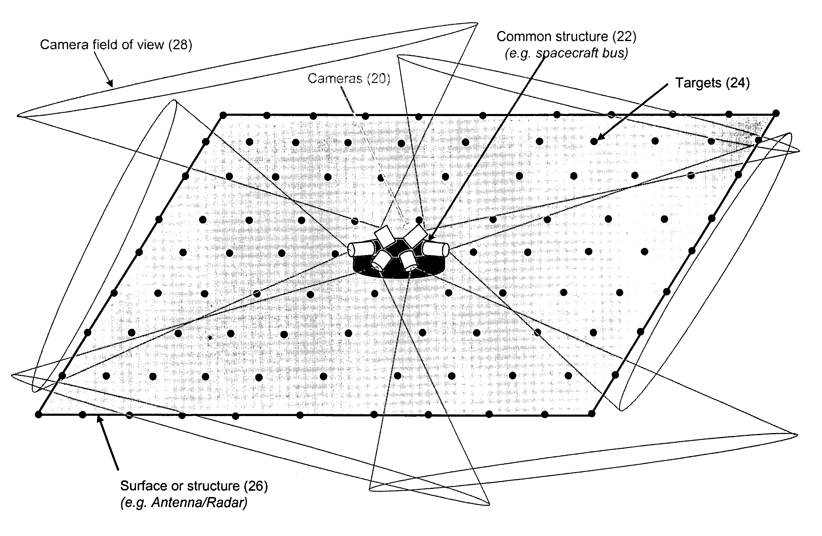
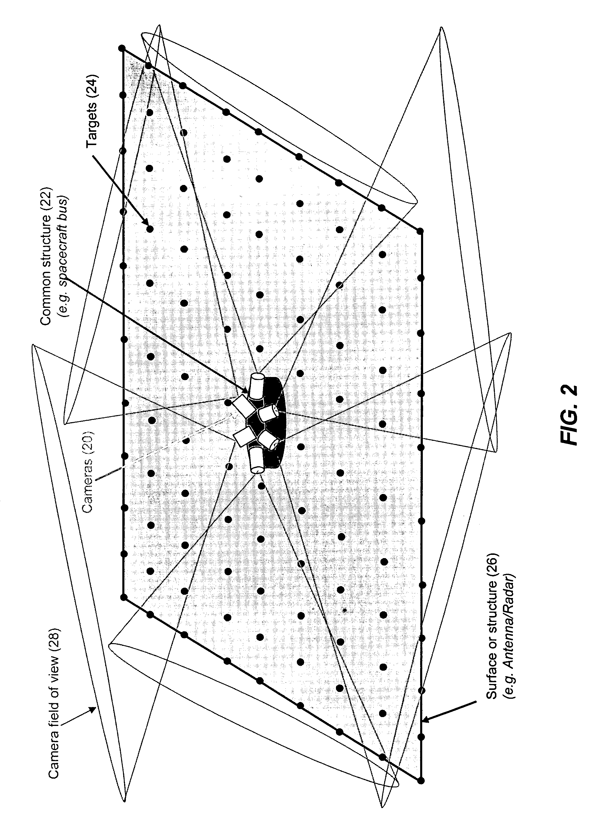
[0036]The present invention in the form of one or more exemplary embodiments will now be described. In one embodiment, the system (herein referred to as the “Shallow Angle Shape Sensor” (SASS) system) utilizes a machine vision system with cameras and targets located on the surface for which the shape is to be determined. With the understanding that deflections normal to the plane of the surface are dominant and sufficient to determine the shape of the surface, the system uses sensor devices, such as, video cameras, located near the plane of the surface and at a shallow angle with the surface to be measured to receive information from the targets.

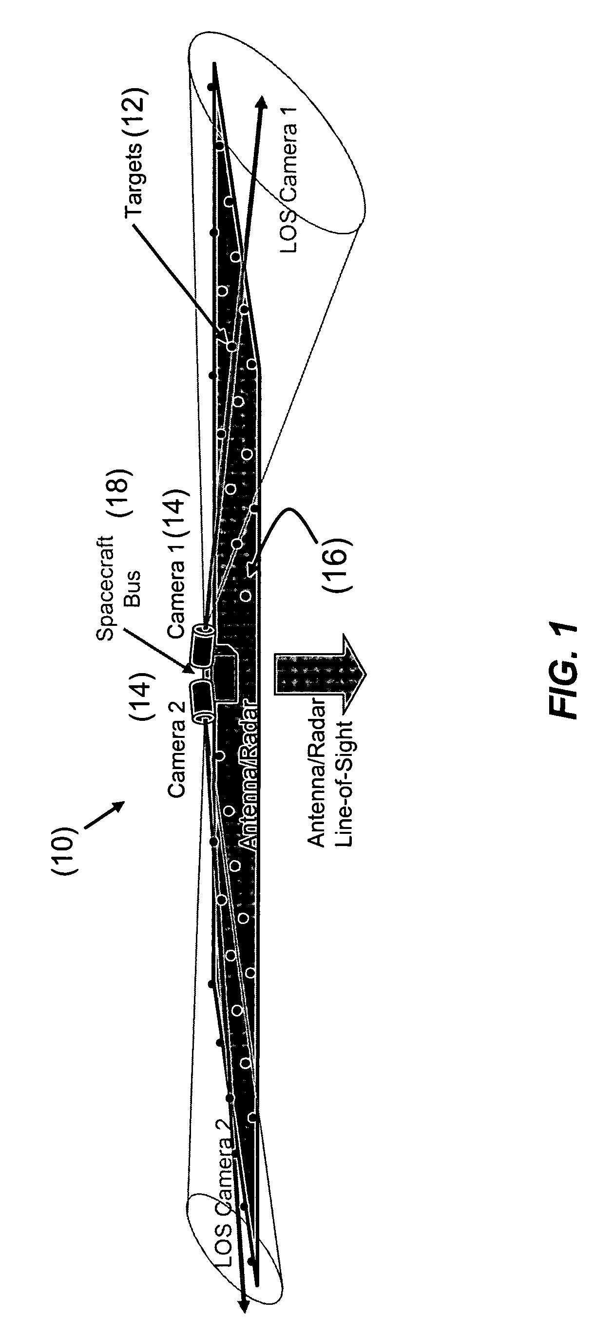
[0037]FIG. 1 illustrates a system 10 representing an embodiment of the present invention. As shown in FIG. 1, the system 10 includes a number of targets 12, two (2) video cameras 14 mounted on a spacecraft bus 18, and a large structure having a planar or quasi-planar surface 16, such as, a radar antenna. The targets 12 are mounted on the bac...


PUM


Abstract

A system for providing shape determination of a planar or quasi-planar surface is disclosed. The system includes a number of targets located on the surface and one or more sensor devices. The sensor devices are configured to monitor the targets and obtain information relating to deflections normal to the plane of the surface. The sensor devices are mounted close to each other and the line-of-sight of each sensor device is at a shallow angle to the plane of the surface. The system further includes processing logic configured to execute a shape reconstruction algorithm based on the information to determine the shape of the surface.

Description

CROSS-REFERENCES TO RELATED APPLICATION(S)[0001]The present application claims the benefit of priority under 35 U.S.C. §119 from U.S. Provisional Patent Application Ser. No. 60 / 613,714 entitled “SHALLOW ANGLE SHAPE SENSOR”, filed on Sep. 29, 2004, the disclosure of which is hereby incorporated by reference in its entirety for all purposes.STATEMENT AS TO RIGHTS TO INVENTIONS MADE UNDER FEDERALLY SPONSORED RESEARCH OR DEVELOPMENT[0002]N / ABACKGROUND OF THE INVENTION[0003]The present invention relates generally to shape determination and, more specifically, to methods and systems for determining the shape of surfaces and / or structures associated with large quasi-planar systems.[0004]Several methods and systems have been proposed to determine the shape of surfaces and / or structures associated with large quasi-planar systems, such as, radar antennas. Such systems include, for example, range-based metrology systems that utilize either optics or radio frequency (RF) and scanning devices or...

Claims


Application Information

Patent Timeline
Patent Type & Authority Patents(United States)
IPC IPC(8): G01C11/12G01B11/24
CPCG01B11/24
Inventor PEDREIRO, NELSONVAN BEZOOIJEN, ROELOF W. H.DEWELL, LARRY
Owner LOCKHEED MARTIN CORP
Why Eureka
Try Eureka