Power supply unit in image forming apparatus

a technology of power supply unit and image forming apparatus, which is applied in the direction of electric variable regulation, process and machine control, instruments, etc., can solve the problems of degrading printing quality, difficult to simply adopt, and oscillating circuit operation, so as to prevent the degradation of the printing quality of the image forming apparatus and stable voltage control

Active Publication Date: 2009-06-16
CANON KK
View PDF14 Cites 26 Cited by
  • Summary
  • Abstract
  • Description
  • Claims
  • Application Information

AI Technical Summary

Benefits of technology

[0006]In view of the above problems in the conventional art, the present invention has an object to realize stable voltage control free from any circuit oscillation in a power supply unit for an image forming apparatus using a piezoelectric transformer, thereby preventing degradation of printing quality of the image forming apparatus.

Problems solved by technology

Unfortunately, the high-voltage power supply apparatus using the conventional piezoelectric transformer cannot sometimes control the output voltage, so the circuit operation oscillates.
Such a phenomenon degrades printing quality.
That is, it is difficult to simply adopt, as a power supply unit in an image forming apparatus, the high-voltage power supply apparatus using the conventional piezoelectric transformer.

Method used


Image

  • Power supply unit in image forming apparatus
  • Power supply unit in image forming apparatus
  • Power supply unit in image forming apparatus

Examples


first embodiment

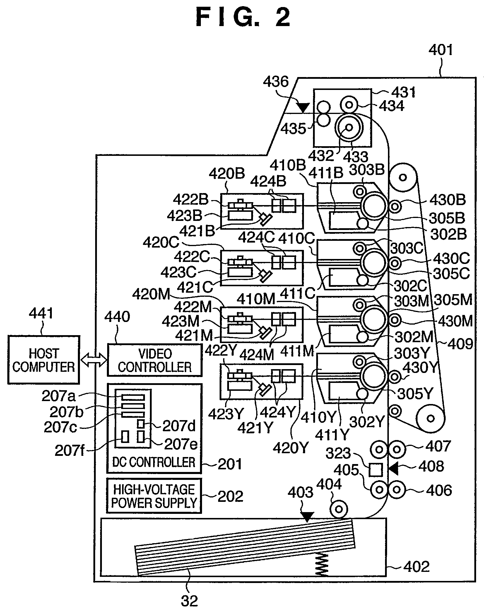
[0021]FIG. 2 is a view showing an arrangement example of a color laser printer serving as an example of an image forming apparatus according to this embodiment. Note that the present invention is not limited to the color laser printer, and can be applied to various image forming apparatuses.

[0022]For example, the image forming apparatus is a color laser printer of a so-called tandem system. In a color laser printer 401 shown in FIG. 2, a deck 402 stores printing paper sheets 32. A paper sensor403 detects the presence / absence of the printing paper sheets 32 in the deck 402. A pickup roller 404 picks up a printing paper sheet 32 from the deck 402. A paper feed roller 405 conveys the printing paper sheet 32 picked up by the pickup roller 404. A retardation roller 406 is paired with the paper feed roller 405 to prevent double feed of the printing paper sheet 32.

[0023]A registration roller pair 407 is arranged downstream of the paper feed roller 405 to synchronously convey the printing p...

second embodiment

[0049]In the above-described first embodiment, the time constants of an output voltage setting signal and output voltage detecting signal are adjusted by appropriately determining the component constants of resistors and capacitors which form the circuit. In this embodiment, a piezoelectric transformer high-voltage power supply unit capable of adjusting the time constants with an arrangement different from that in the above first embodiment will be described below with reference to FIGS. 6, 7, and 8A and 8B. Note that a description of the same arrangement as that in the first embodiment will be omitted.

[0050]This embodiment differs from the first embodiment in that firmware adjusts the time constant of an output voltage setting signal.

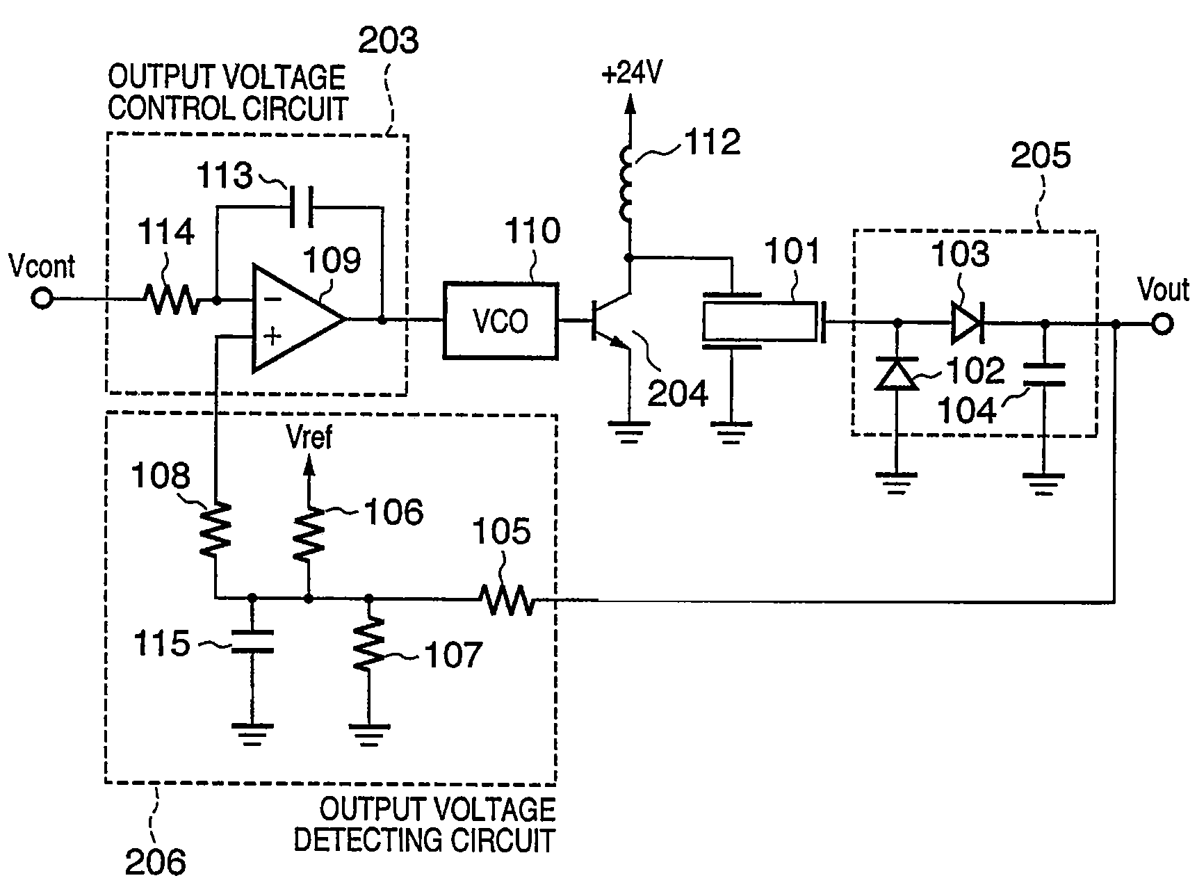
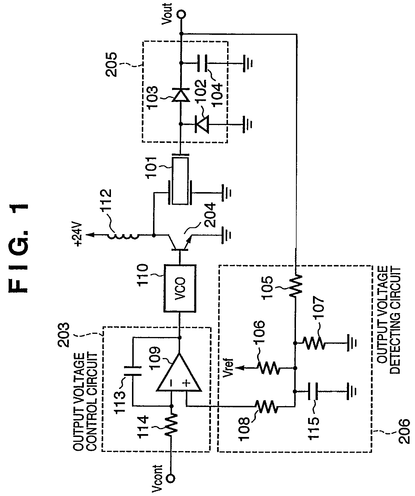
[0051]FIG. 6 is a block diagram showing the arrangement of the high-voltage power supply unit using the piezoelectric transformer according to this embodiment. The arrangement shown in FIG. 6 is almost the same as that shown in FIG. 4 according to the ...

third embodiment

[0056]In the above-described second embodiment, the time constant Tcont of the output voltage setting signal Vcont is adjusted by the firmware, and the time constant Tsns of the output voltage detecting signal Vsns is adjusted by the circuit constants. In this embodiment, a piezoelectric transformer high-voltage power supply unit capable of adjusting a time constant by using an arrangement developed from that of the above second embodiment will be described below with reference to FIGS. 9 and 10. Note that a description of the same arrangement as that in the first embodiment will be omitted.

[0057]This embodiment is different from the second embodiment mainly in that an output voltage detecting signal Vsns is input to an MPU 207 and compared in the MPU 207 with an output voltage setting signal Vcont to be output.

[0058]FIG. 9 is a block diagram showing the arrangement of a high-voltage power supply unit using a piezoelectric transformer according to this embodiment. A D / A terminal 207...


PUM


Abstract

A power supply unit in an image forming apparatus is provided. The power supply unit includes a piezoelectric transformer, an output voltage detecting circuit which detects the output voltage of the piezoelectric transformer, an output voltage control circuit which controls an output voltage from the piezoelectric transformer, and includes a comparator which receives an output voltage setting signal, together with an output voltage detecting signal fed back from the output voltage detecting circuit, to compare the output voltage setting signal and the output voltage detecting signal. The power supply unit also includes a driving frequency supplying circuit which generates a driving frequency signal of the piezoelectric transformer in accordance with a comparison result by the comparator, and supplies the driving frequency signal to the piezoelectric transformer. The time constant of the output voltage control circuit is longer than the time constant of the output voltage detecting circuit.

Description

FIELD OF THE INVENTION[0001]The present invention relates to a power supply unit in an image forming apparatus.BACKGROUND OF THE INVENTION[0002]When an image forming apparatus of an electrophotographic method adopts a direct transfer system of transferring an image by bringing a transfer member into contact with a photoconductor, the transfer member uses a conductive rubber roller (transfer roller) having a conductive shaft to rotate and drive the transfer member while matching the process speed of the photoconductor. A voltage applied to the transfer member is a DC bias voltage. At this time, the polarity of the DC bias voltage is identical to that of a transfer voltage for general corona discharge.[0003]To achieve satisfactory transfer using the transfer roller, a voltage of generally 3 kV or more (the required current is several μA) must be applied to the transfer roller. This high voltage necessary for the image forming process is conventionally generated using a wire-wound elec...

Claims


Application Information

Patent Timeline
Patent Type & Authority Patents(United States)
IPC IPC(8): G03G15/00H01L41/00G03G21/00G03G21/14H02M3/24
CPCG03G15/80
Inventor NAGASAKI, OSAMUYAMAGUCHI, ATSUHIKONAKAMORI, TOMOHIROUCHIYAMA, TAKEHIROYASUKAWA, KOUJINAMIKI, TERUHIKOMURATA, HIROKI
Owner CANON KK
Why Eureka
Try Eureka