Multi-band RF receiver

a receiver and multi-band technology, applied in the field of wireless communication systems, can solve the problems of short transmission distance and inconvenience of 802.11a

Active Publication Date: 2009-06-16
REALTEK SEMICON CORP
View PDF11 Cites 9 Cited by
  • Summary
  • Abstract
  • Description
  • Claims
  • Application Information

AI Technical Summary

Benefits of technology

[0011]Furthermore, a multi-band receiver is disclosed. The multi-band comprises: an amplifier for amplifying a received signal and thereby outputting an amplified signal, wherein the received signal has a first signal corresponding to a first frequency and a second signal corresponding to a second signal; and a mixer coupled to the amplifier, comprising: a multi-band LC tank for providing a first impedance at the first frequency and a second impendence at the second frequency to remove a common-mode noise of the amplified signal; and a mixing circuit coupled to the multi-band LC tank for converting the amplified signal into an output signal.

Problems solved by technology

Furthermore, 802.11a has the disadvantage of short transmission distance and is inconvenient, because the 5 GHz transmission band is not available in some regions.

Method used


Image

  • Multi-band RF receiver
  • Multi-band RF receiver
  • Multi-band RF receiver

Examples


Embodiment Construction

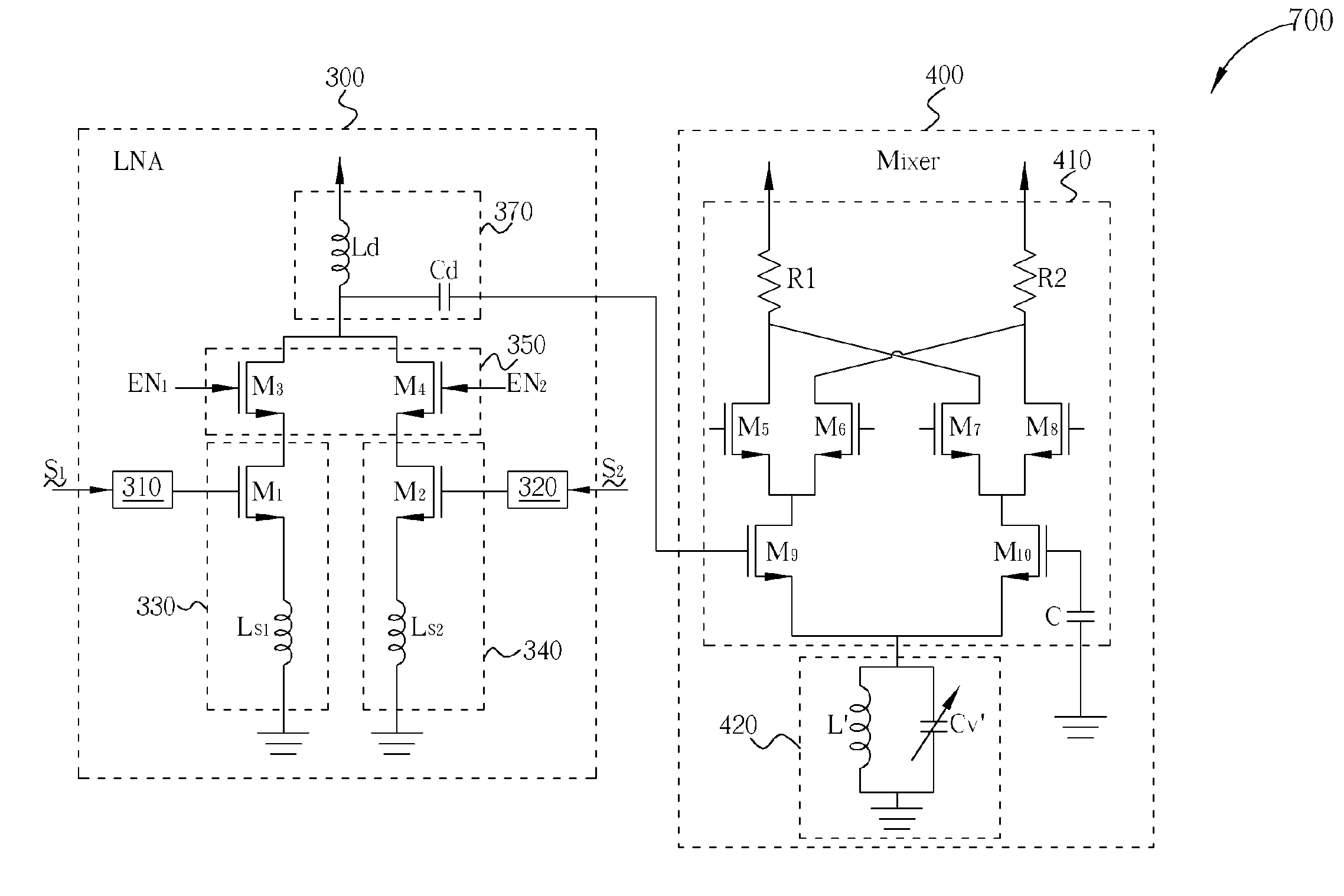
[0017]Please refer to FIG. 3, which is a diagram of a multi-band receiver 700 according to the present invention. The multi-band receiver 700 comprises an LNA 300 and a mixer 400. As shown in FIG. 3, the LNA 300 comprises a 2.4 G matching network 310, a 5 G matching network 320, a gain cell 330 coupled to the 2.4 G matching network 310, a gain cell 340 coupled to the 5 G matching network 320, a switching circuit 350 coupled to the gain cells 330, 340, and a loading circuit 370 coupled to the switching circuit 350. Here, the matching circuits 310, 320 are respectively utilized to receive input signals S1, S2 with specific frequencies (2.4 GHz and 5 GHz), where the functions and structures of the matching circuits 310, 320 are well known, and thus omitted here. The gain cells 330, 340 cooperate with the loading circuit 370 to amplify the received input signal S1, S2. Please note that in this embodiment, the loading circuit 370 is utilized to fixedly provide a specific load to the gain...


PUM


Abstract

A multi-band receiver is disclosed. The multi-band receiver includes a low-noise amplifier (LNA) and a mixer. The LNA includes a switched receiving circuit, a loading circuit, and a switching circuit. The switched receiving circuit has a first receiving circuit for receiving a first signal corresponding to a first frequency, and a second receiving circuit for receiving a second signal corresponding to a second frequency. The loading circuit is utilized for providing a specific load to the switched receiving circuit. The switching circuit is used for controlling whether the first signal or the second signal is transferred to the loading circuit. The mixer is coupled to the low-noise amplifier for receiving an output signal generated from the LNA and for down-converting the output signal.

Description

BACKGROUND OF THE INVENTION[0001]1. Field of the Invention[0002]The invention relates to a wireless communication system, and more particularly, to a multi-band receiver utilized in a wireless communication system.[0003]2. Description of the Prior Art[0004]WLAN is a fast-developing and fast-changing technique both in its standard and its applications. For example, 802.11a utilizes a 5 GHz transmission band, but 802.11b and 802.11g utilize a 2.4 GHz transmission band. Furthermore, 802.11a has the disadvantage of short transmission distance and is inconvenient, because the 5 GHz transmission band is not available in some regions. Therefore, few products are designed which will only support 802.11a. The next generation of WLAN techniques and WLAN products will simultaneously support 802.11a and 802.11g so that the transmission efficiency can be raised and the number of users can be increased. Furthermore, the transmission quality demands can be met.[0005]Nowadays, a dual-band / multi-ban...

Claims


Application Information

Patent Timeline
Patent Type & Authority Patents(United States)
IPC IPC(8): H04B1/26H04B1/28
CPCH04B1/0067
Inventor LIN, YING-YAOLIN, YING-HSI
Owner REALTEK SEMICON CORP
Why Eureka
Try Eureka