Surface acoustic wave based humidity sensor apparatus with integrated signal conditioning

a humidity sensor and signal conditioning technology, applied in the direction of resistive material coating, material resistance, mechanical means, etc., can solve the problems of 2% or less, inherent accuracy issues, slow response time, etc., to improve the effect of improving the coupling rate of the surface acoustic wave and improving the resolution and sensitivity of the sensor

Inactive Publication Date: 2011-09-13
HONEYWELL INT INC
View PDF17 Cites 6 Cited by
  • Summary
  • Abstract
  • Description
  • Claims
  • Application Information

AI Technical Summary

Benefits of technology

[0011]It is a further aspect of the present invention to provide for a SAW-based humidity sensor having common mode delay lines with two sets of IDTs in order to eliminate common mode noise.
[0013]The aforementioned aspects and other objectives and advantages can now be achieved as described herein. A SAW-based humidity sensor apparatus with integrated signal conditioning on the same substrate and method forming such an apparatus is disclosed. Micro-electronic circuitry can be processed on a substrate (e.g., silicon) to obtain on-chip signal conditioning internally. The substrate can be covered with a protective layer (e.g., silicon nitride layer) to protect the micro-electronic circuitry from damage. Surface acoustic wave media (e.g., ZnO film) can be then coated on top of the protective layer. A humidity sensitive film and two sets of IDTs can then be deposited on the surface acoustic wave media. The humidity sensitive film absorbs moisture and alters the receiving frequency at the two sets of IDTs. The output from the two sets of IDTs can be processed by the micro-electronic circuitry, which eliminates common mode noise and generates an output signal proportional to the humidity value tested.
[0014]The thickness of the ZnO film, for example, can be optimized to raise the coupling rate of the surface acoustic wave(s) and to improve the resolution and sensitivity of the sensor. The two sets of IDTs can include a reference IDT set and a sensing IDT set. The micro-electronic circuitry can be further configured to include a mixer, an intermediate filter and a phase lock loop component. The output of the sensing IDT set and the reference IDT set can be fed into the mixer. The receiving frequency at the sensing IDT set and the reference IDT set changes when the pressure and temperature change.
[0015]The common mode noise can be eliminated by the mixer and hence, the output frequency is only proportional to the humidity value tested. Then, the frequency signal can be fed into the intermediate filter and phase lock loop component. The frequency signal can be converted into an amplitude signal for final application. The disclosed single chip solution with SAW-based humidity sensor integrated with micro-electronic circuitry therefore provides a quick response time (e.g., <1 S) and better accuracy (e.g., 1%), which is suitable for instrumentation in high-end applications.

Problems solved by technology

Such capacitive humidity sensors, however, possess a number of disadvantages such as a slow response time, inherent accuracy issues (e.g., 2% or less), device degradation over a long period (e.g., over a 5 year period) and a relatively high hysteresis.
These disadvantages can constrain the application of the capacitive humidity sensor in high-end applications such as, for example, weather stations, instrumentation and industrial control in semiconductor foundries.
Hence, it is not possible to integrate the signal conditioning circuitry on the same chip, as SAW sensing devices rely on piezoelectric materials to transform the electrical energy to surface acoustic waves and to interrogate with the humidity sensitive film and also sense the humidity value tested.
Such a solution possesses inherent disadvantages such as, for example, a low signal-to-noise and is relatively complex and expensive to package.
However, because the output frequency of the IDT is also sensitive to temperature and pressure, a single IDT set cannot distinguish between differences in pressure, temperature and humidity values.

Method used


Image

  • Surface acoustic wave based humidity sensor apparatus with integrated signal conditioning
  • Surface acoustic wave based humidity sensor apparatus with integrated signal conditioning
  • Surface acoustic wave based humidity sensor apparatus with integrated signal conditioning

Examples


Embodiment Construction

[0021]The particular values and configurations discussed in these non-limiting examples can be varied and are cited merely to illustrate at least one embodiment and are not intended to limit the scope thereof.

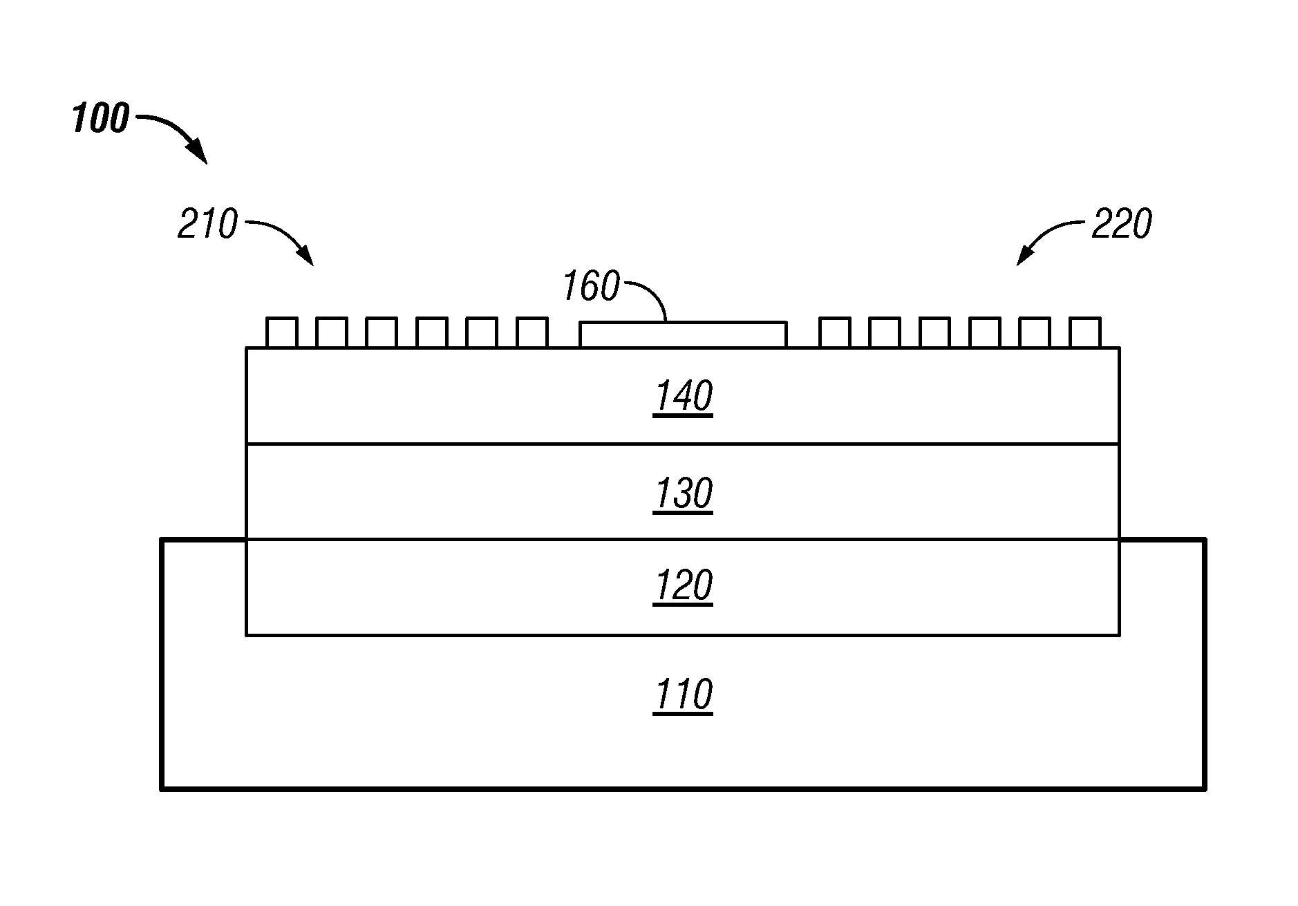
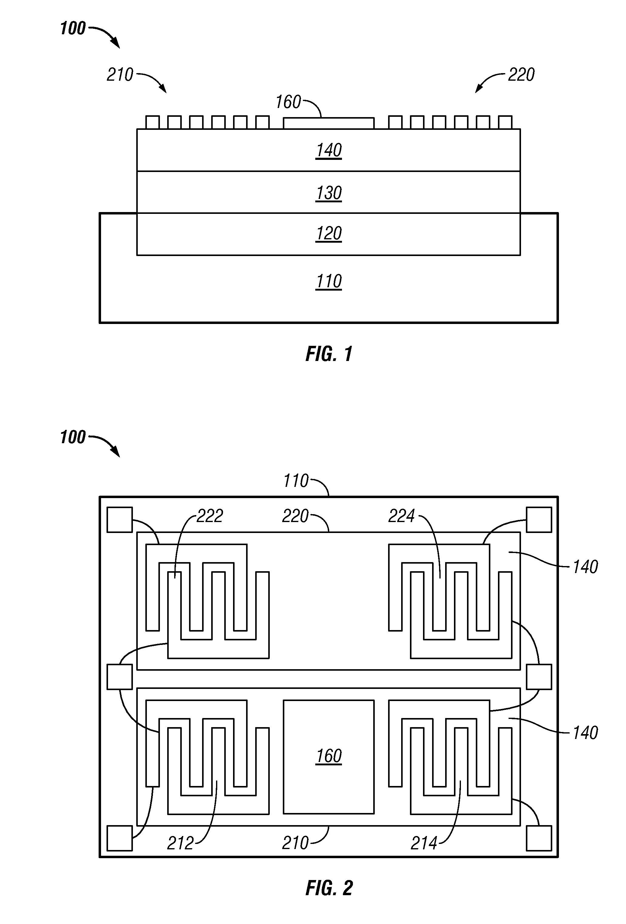
[0022]FIG. 1 illustrates a cross sectional view of a SAW-based humidity sensor apparatus 100, which can be implemented in accordance with a preferred embodiment. The SAW-based humidity sensor apparatus 100 generally includes a micro-electronic circuit 120 that can be processed at a silicon substrate 110. A protective layer 130 of, for example, silicon nitride, can be deposited on top of the micro-electronic circuit 120 to protect the micro-electronic circuit 120 from damage. The micro-electronic circuit 120 can be processed at the silicon substrate 110, which is compatible with normal electronic processes.

[0023]Surface acoustic wave media 140 (e.g., a ZnO film) can then be deposited on top of the protective layer 130. The ZnO film thus acts as surface acoustic wave media. Acous...


PUM

PropertyMeasurementUnit
response timeaaaaaaaaaa
thicknessaaaaaaaaaa
humidityaaaaaaaaaa

Abstract

A SAW-based humidity sensor apparatus with integrated signal conditioning on the same substrate. A micro-electronic circuit can be processed at a silicon substrate to obtain on-chip signal conditioning internally and the silicon substrate can be covered with a protective layer of, for example, silicon nitride. Surface acoustic wave media (e.g., a ZnO film) can be coated on top of the protective layer. A humidity sensitive film and two sets of interdigital transducers can then be deposited on the surface acoustic wave media. The humidity sensitive film absorbs moisture and changes the receiving frequency at the two sets of interdigital transducers. The output from the two sets of interdigital transducers can be processed by the micro-electronic circuit, which eliminates common mode noise and generates an output signal proportional to the humidity value tested.

Description

TECHNICAL FIELD[0001]Embodiments are generally related to sensing devices and applications. Embodiments are also related to humidity sensors and SAW (Surface Acoustic Wave) sensing devices. Embodiments are further related to SAW-based humidity sensor with integrated signal conditioning.BACKGROUND OF THE INVENTION[0002]Humidity sensors are widely utilized for humidity and air quality measurement in a variety of applications (e.g., automotive for comfort, safety and power train, home appliances for moisture and temperature control, energy efficiency, humidity switches, HVAC, etc.). Humidity can be measured utilizing a number of techniques such as, for example, wet bulb psychrometer, chilled mirror dew point, saturated salt solutions, resistive RH sensors, capacitive RH sensors, and SAW-based humidity.[0003]The majority of prior art capacitive humidity sensors with on-chip signal conditioning internally connected with a humidity capacitive element possess advantages such as a high sign...

Claims


Application Information

Patent Timeline
Patent Type & Authority Patents(United States)
IPC IPC(8): G01N27/12
CPCG01N29/022G01N29/245G01N2291/02845G01N2291/0423
Inventor ZHANG, WENWEI
Owner HONEYWELL INT INC
Why Eureka
Try Eureka