Paint delivery and application system and method

a technology of application system and paint, which is applied in the direction of packaging, pipes, pipes, etc., can solve the problems of waste of paint, increased cost, and electrical or electrostatic charge applied to the electrically conductive, so as to reduce paint and solvent losses, accurate control, and reduce cost

Active Publication Date: 2009-06-23
DURR SYST INC
View PDF12 Cites 23 Cited by
  • Summary
  • Abstract
  • Description
  • Claims
  • Application Information

AI Technical Summary

Benefits of technology

[0009]As set forth above, the paint delivery and application systems and methods of this invention may be utilized to apply electrically conductive paint utilizing a conventional electrostatic rotary atomizer and is particularly, but not exclusively, adaptable to robotic paint applicators and overhead and side mounted paint applicators. The paint delivery and application systems and methods of this invention significantly reduce cycle time and substantially reduces or eliminates waste paint.
[0010]One preferred embodiment of the paint delivery and application system of this invention includes a color changer or paint supply switching device at ground potential preferably having at least two sources of paint under pressure, at least two paint canisters, a paint applicator, a first pair of separate supply lines connecting the paint supply switching device and the paint canisters, and a second pair of separate supply lines connecting the canisters to the paint applicator (in most cases an atomizer). Thus, with this embodiment of the paint delivery and application system of this invention, a first paint may be supplied from a first paint canister to the paint applicator while a second paint is supplied from the paint supply switching device to a second canister, significantly reducing the cycle time. As will be understood, the cycle time may be further reduced by utilizing three or more paint canisters connected in parallel between the paint supply switching device and the paint applicator. However, one preferred embodiment of this paint delivery and application system of this invention includes at least two paint canisters connected in parallel by paint supply lines between the color changer or paint supply switching device and the paint applicator.

Problems solved by technology

There are several problems associated with the prior paint delivery and application systems described above, particularly in mass production applications, wherein the part to be painted is generally supplied to the applicator in a paint spray booth by a conveyor requiring a short cycle time.
As will be understood by those skilled in this art, the longer the cycle time, that is the time required to change from a first paint to a second paint, the greater the expense.
Another problem is associated with the electrical or electrostatic charge applied to the electrically conductive paint by the paint applicator during application, particularly with rotary electrostatic paint atomizers of the type commonly used in mass production applications.
This presents a particular problem when attempting to reduce cycle time.
Other problems with conventional paint supply and application systems include waste of paint, cycle time for cleaning and flushing of the paint applicator and paint lines and changing of paint colors, particularly including but not limited to robotic paint systems.
Other problems associated with paint delivery and application systems of the type described herein, particularly for mass production applications, including automotive applications, generally relate to the precise metering of liquid coating or paint applied to the part because of differences in the temperature and viscosity of the liquid coating and different parts may be painted in the same line.

Method used


Image

  • Paint delivery and application system and method
  • Paint delivery and application system and method
  • Paint delivery and application system and method

Examples


Embodiment Construction

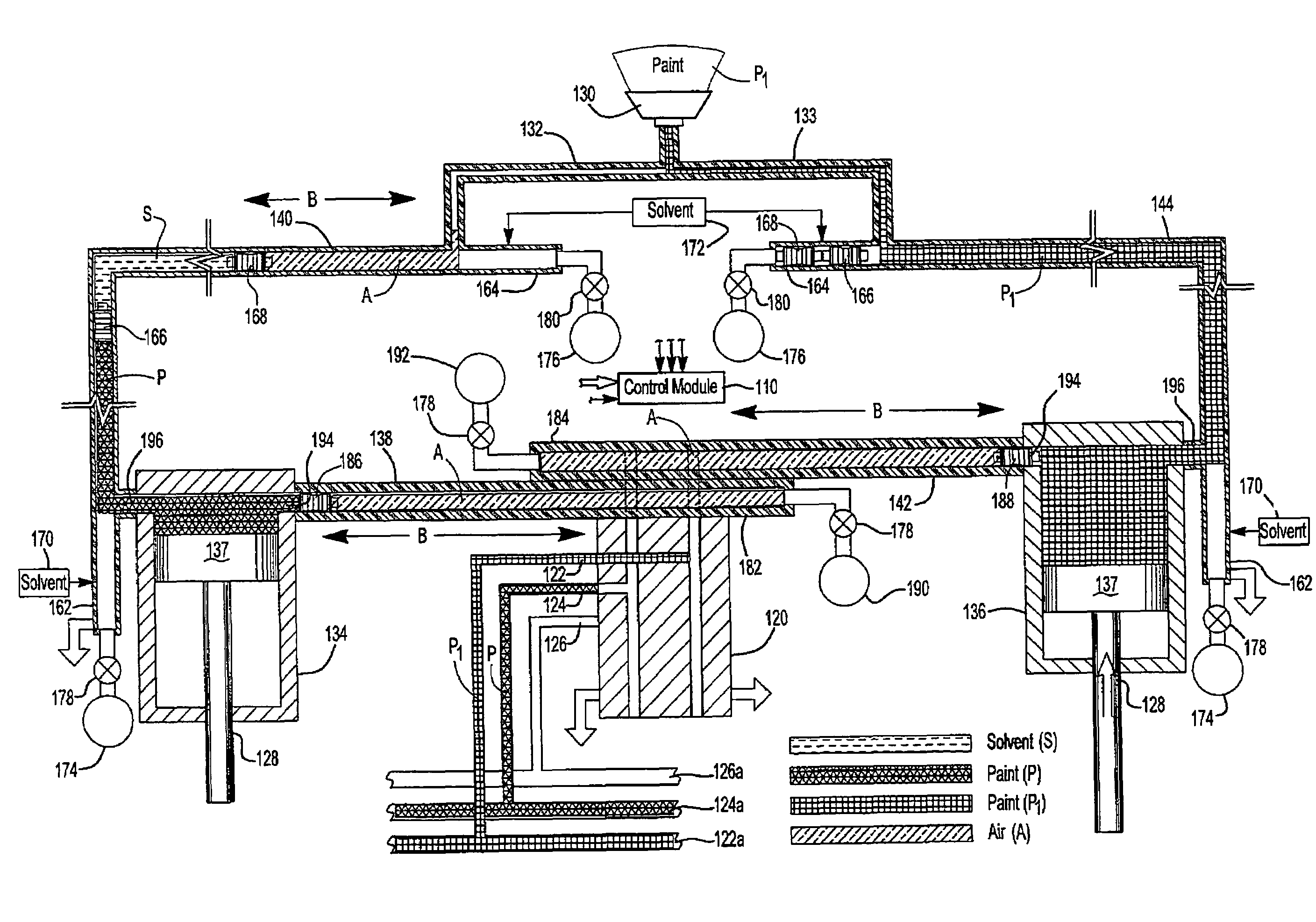
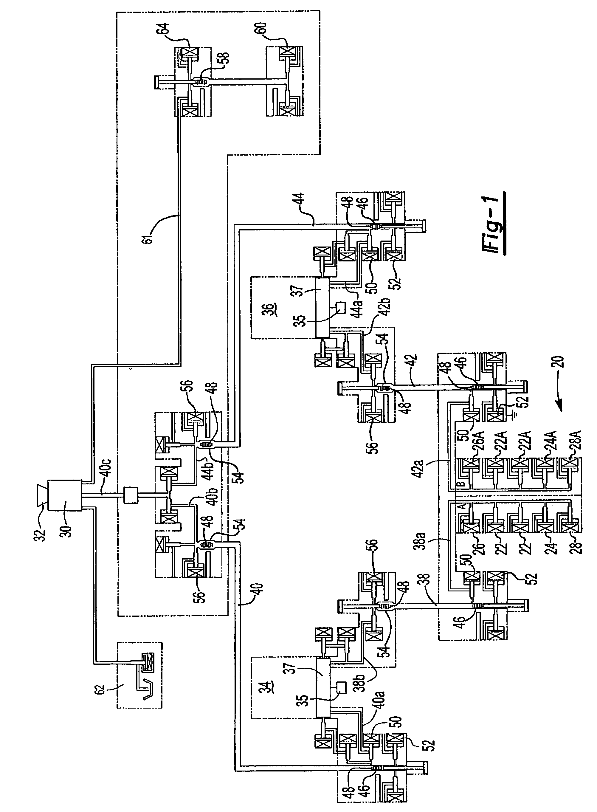
[0028]The schematic or fluid diagram of FIG. 1 illustrates the components of one embodiment of the paint delivery and application system of this invention. The paint delivery and application system illustrated in FIG. 1 includes a color changer or paint supply switching device 20 at ground potential including a plurality of ports each connected to a source of paint under pressure 22, a port connected to a source of solvent under pressure 24, ports connected to a source of air or pneumatic pressure 26 and a solvent recovery port 28. The color changer 20 in this embodiment of the invention may be generally conventional except that in the disclosed embodiment, the color changer 20 is divided in two identical components in parallel, wherein the second component includes the suffix “A” for ease of reference. The number of components will depend upon the number of paint canisters. As will be understood, the number of ports 22 which receive paint under pressure will depend upon the number ...


PUM

PropertyMeasurementUnit
cycle timeaaaaaaaaaa
movementaaaaaaaaaa
pressureaaaaaaaaaa

Abstract

A paint delivery and application system including a color changer, at least two paint canisters and a paint applicator, a first pair of supply lines connected between the color changer and the paint canisters and a second pair of supply lines connecting the paint canisters and the paint applicator, wherein the paint canisters operate in tandem permitting delivery of a first paint to one of the paint canisters while a second paint canister is electrically isolated from the color changer and is delivering paint to the applicator. In one disclosed embodiment, the delivery line from the paint canisters to the applicator includes two pigs and solvent is delivered between the pigs, such that this system is self purging.

Description

FIELD OF THE INVENTION[0001]The present invention relates to paint or coating delivery and application systems using pigging technology and methods of delivering and applying paint which significantly reduce cycle time between applications to a substrate or a plurality of substrates using multiple coating materials or colors and substantially eliminating waste of paint.BACKGROUND OF THE INVENTION[0002]The prior art discloses numerous paint delivery and application systems including systems using pigging technology. Such systems may be used to apply seriatim paints of different colors, for example, to a plurality of substrates, such as vehicle bodies on a moving conveyor in a paint spray booth. The term “paint,” as used herein, includes solvent or water base paints used to paint or coat a substrate and generically any coating, including protective coatings, which may be applied to a substrate using an applicator, such as a sprayer or rotary atomizer. Depending on its function in the ...

Claims


Application Information

Patent Timeline
Patent Type & Authority Patents(United States)
IPC IPC(8): B65B1/04B05B15/02B05D1/02B05B5/16B05B12/14F16L11/12
CPCB05B5/1616B05B5/1625B05B5/1633B05B5/1675B05B12/14B05B12/1481F16L11/12B05B12/149F16L2101/20F16L2101/40
Inventor HERRE, FRANKMELCHER, RAINERMARTIN, HERBERTBAUMANN, MICHAELMICHELFELDER, MANFREDOSTIN, RICHARD M.HELDT, ROBERT F.HERING, JOACHIMNOLTE, HANS JURGEN
Owner DURR SYST INC
Why Eureka
Try Eureka