Pressure container

a technology of pressure containers and pressure chambers, applied in the field of pressure containers, can solve the problems of high stress concentration in resinous liner, insufficient sealing ability of pressure containers, and thereby broken or damaged liner, and achieve the effect of improving sealing ability

Inactive Publication Date: 2009-06-23
TOYODA GOSEI CO LTD
View PDF18 Cites 31 Cited by
  • Summary
  • Abstract
  • Description
  • Claims
  • Application Information

AI Technical Summary

Benefits of technology

[0015]The present invention has been made in consideration of the above situation, and it is to provide a pressure

Problems solved by technology

Even in such pressure containers, however, the stress concentration in the resinous liner is great and the liner may be thereby broken or damaged.
Anyhow, the seal ability of the pressure containers is not always satisfactory, and it is desired to develop pressure containers of improved seal ability and increased reliability.
However, since iron has a large specific gravity, 7.9, gas containers formed of iron are problematic in that their weight is large.
For example, when such gas containers are filled with fuel gas and mounted on vehicles, it is problematic in that the fuel expenses for vehicles increase.
Not limit

Method used


Image

  • Pressure container
  • Pressure container
  • Pressure container

Examples


embodiment 1

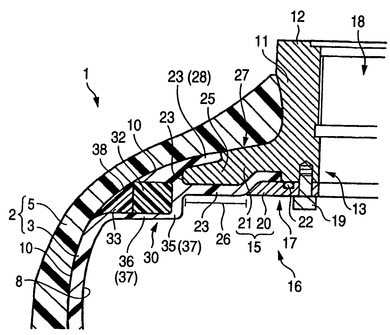
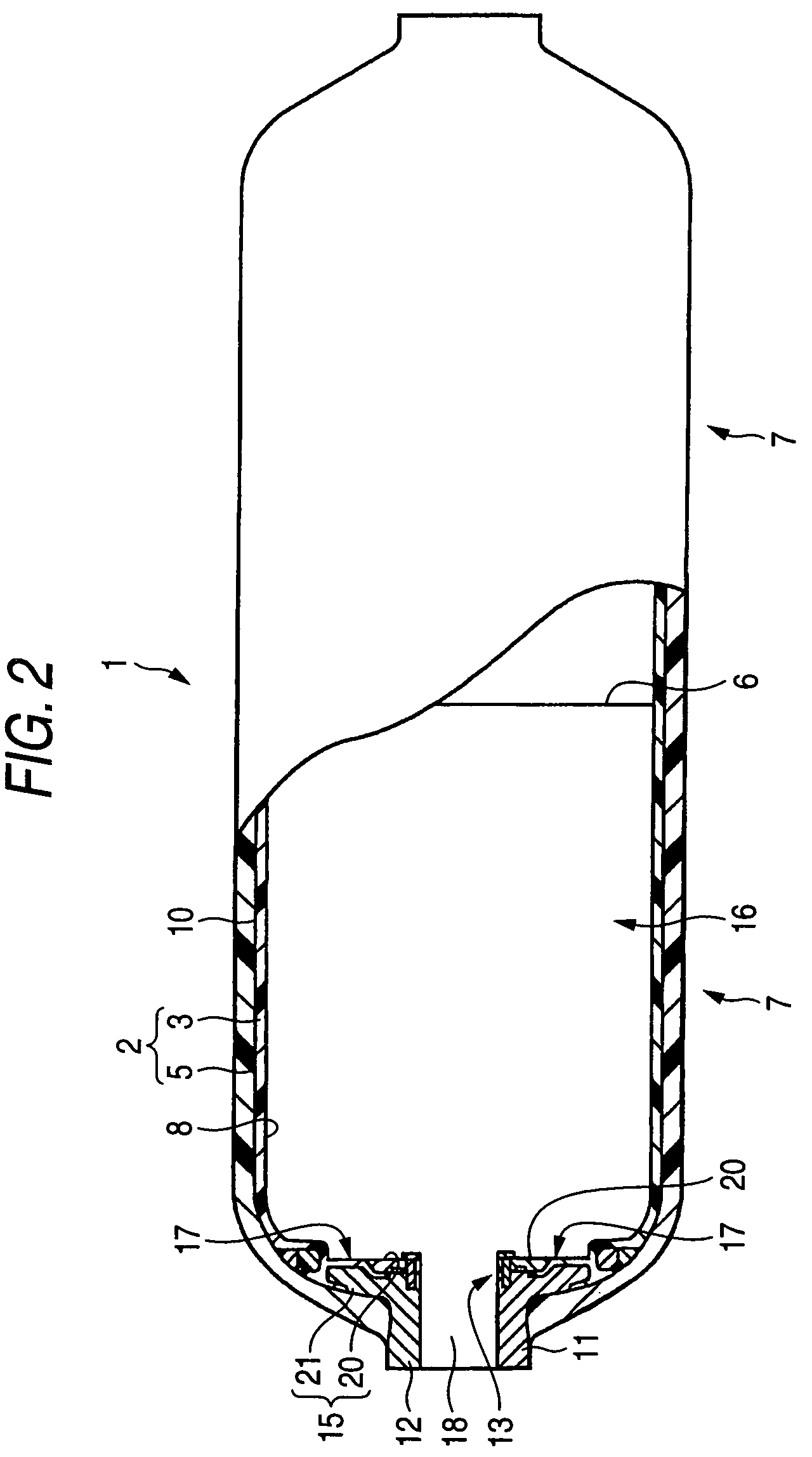
[0088]Embodiment 1 is to demonstrate a pressure container which has a ring-shaped constraint member around the self-sealing part and in the outer periphery of the liner and has an easily-displaceable part 37 on the outer periphery of the self-sealing part of the liner in the radial direction thereof. FIG. 2 shows a schematic cross-sectional view of the pressure container of Embodiment 1; and FIG. 3 is a partly-enlarged view of FIG. 2.

[0089]Of the pressure container of Embodiment 1, the container body 2 is composed of a constraint layer 5 and a liner 3 attached on the inner surface of the constraint layer 5. The liner 3 of the container body 2 is prepared as two parts 7 of the same shape that are split at the body center 6, and the two parts 7 are hot-sealed and integrated into the liner 3.

[0090]The liner 3 is formed of PPS (polyphenylene sulfide), and this covers the inner surface 8 of the container body 2. The constraint layer 5 is formed of FRP that contains carbon fibers and epox...

embodiment 2

[0105]Embodiment 2 is to demonstrate a pressure container that is fabricated in the same manner as in Embodiment 1 except that the constraint member is embedded in the liner and is integrated with the liner. FIG. 4 is a partly-enlarged, schematic cross-sectional view of the pressure container of Embodiment 2.

[0106]In the pressure container 40 of Embodiment 2, the constraint member 41 is embedded in the liner 42 and is integrated with the liner 42. Therefore, the process for producing the pressure container in this Embodiment may be simplified. In addition, like in Embodiment 1, the pressure container of this Embodiment also has the constraint member 41 and the easily-displaceable part 43, and therefore the bonding between the self-sealing part 45 and the flange 46 in this is also kept good.

embodiment 3

[0107]Embodiment 3 is to demonstrate a pressure container that is the same as that of Embodiment 1 except that the constraint member is integrated with the constraint layer and the flange is the flange body alone. FIG. 5 is a partly-enlarged, schematic cross-sectional view of the pressure container of Embodiment 3.

[0108]In the pressure container 47 of Embodiment 3, the flanges 52 is the flange body 44 alone, and the flange body 44 is processed to have a groove 39 in the circumferential direction thereof. In the pressure container 47 of this Embodiment 3, a part of the self-sealing part 51 is formed to be filled inside the groove 39, and therefore the self-sealing part 51 is held by the groove 39.

[0109]In the pressure container 47 of Embodiment 3, the constraint member 48 is integrated with the constraint layer 49. Therefore, the process for producing the pressure container in this Embodiment may be simplified. In addition, like in Embodiment 1, the pressure container of this Embodim...


PUM

PropertyMeasurementUnit
Pressureaaaaaaaaaa
Diameteraaaaaaaaaa
Impact resistanceaaaaaaaaaa

Abstract

A flange is provided at the opening metal of a pressure container, and it extends toward the periphery of the container body at the bonding part thereof at which it bonds to the container body. The liner of the pressure container has a self-sealing part at which it abuts the flange to be sealed up together. On the outer peripheral side of the self-sealing part, a ring-shaped constraint member is provided in the outer periphery of the liner, and the constraint member is to restrict the diameter expansion of the liner to be caused by the expansion of the container body. The liner has an easily-displaceable part that is readily elongable and deformable, at the outer periphery thereof in the radial direction of the self-sealing part.

Description

[0001]The present application is based on Japanese Patent Applications Nos. 2002-381195, 2003-20412 and 2003-92448, the entire contents of which are incorporated herein by reference.BACKGROUND OF THE INVENTION[0002]1. Field of the Invention[0003]The present invention relates to pressure containers that are filled with various compressed gases such as CNG (compressed natural gas), various liquefied gases such as LNG (liquefied natural gas), LPG (liquefied petroleum gas), high-pressure hydrogen gases and other various pressurized substances.[0004]2. Related Art[0005]For pressure containers that are filled with various pressurized substances such as various compressed gases and various liquefied gases, generally employed are those that comprise a hollow resinous liner and a metallic opening metal fitted thereto. For ensuring the pressure resistance of pressure containers, in general, the outer peripheries of the liner and the opening metal are coated with a reinforcing member that sati...

Claims


Application Information

Patent Timeline
IPC IPC(8): F17C1/00B65D1/42B65D6/00F17C1/16
CPCF17C1/16F17C2203/0604F17C2203/066F17C2205/0305F17C2221/012F17C2221/033F17C2221/035F17C2223/0123F17C2223/0153Y02E60/321Y02E60/32
Inventor SUZUKI, TETSUYAKOMADA, MINORUFUJIHARA, KAZUOKONDO, YOSHIAKIMAENO, TAKASHIKOMATSU, ISAMU
Owner TOYODA GOSEI CO LTD
Why Eureka
Try Eureka