
LED lighting for glass tiles

a technology of led lighting and glass tiles, applied in the direction of instrumentation, building repair, coupling device connection, etc., can solve the problems of high installation cost of fiber optic lighting systems, short service life of bulbs, and high labor intensity of workers

Inactive Publication Date: 2009-06-23
NEW HORIZON DESIGNS
View PDF19 Cites 40 Cited by
  • Summary
  • Abstract
  • Description
  • Claims
  • Application Information

AI Technical Summary

Benefits of technology

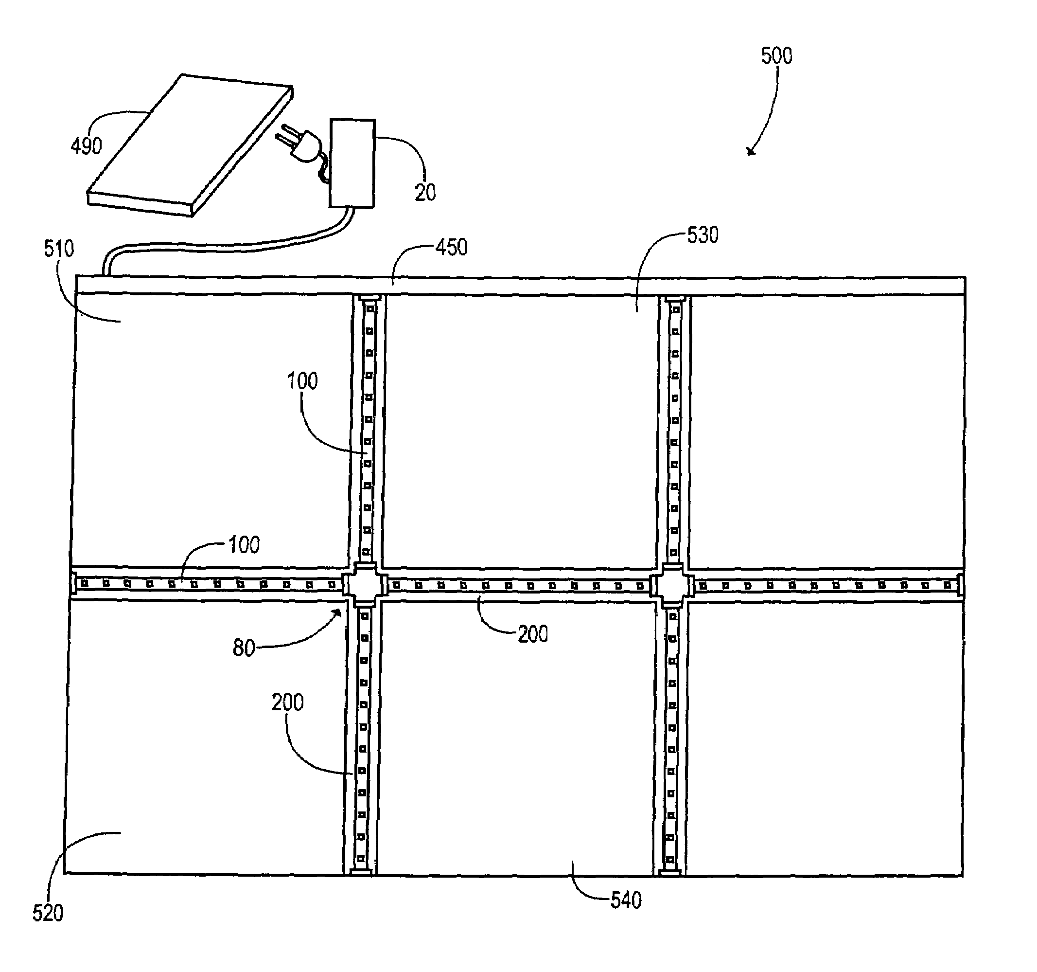
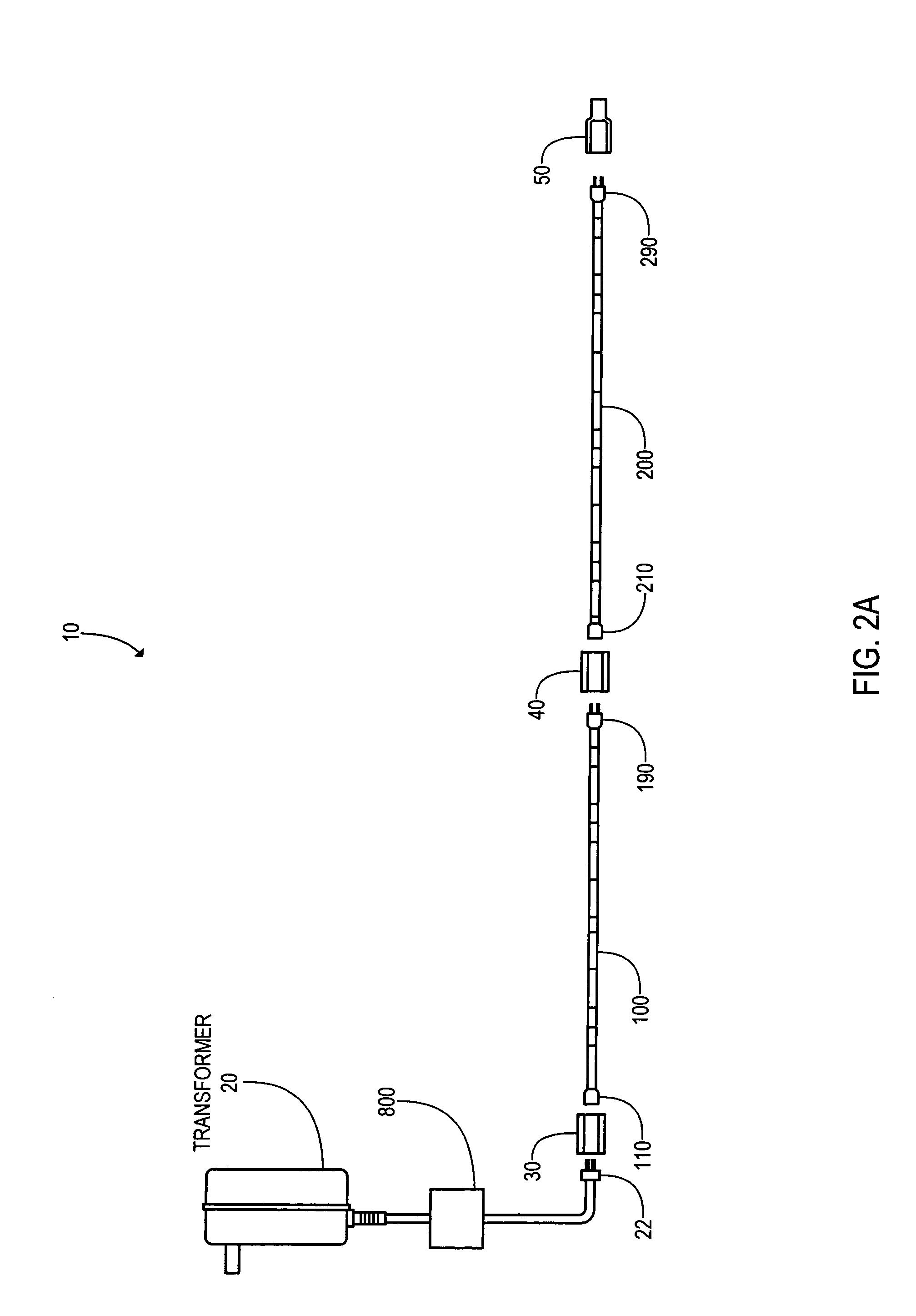
"The present invention provides devices, apparatus, systems, and methods for installing LED lights on glass tiles and blocks. The LED strips are flexible and can be bent up to 45 degrees, and they come in a variety of lengths and can be connected together. The LED strips can be monochromatic or change colors throughout the color spectrum. The LEDs can be placed between the tiles and the grout lines, and the grout can be easily removed and replaced. The LED strips are powered by a low voltage transformer system that can be connected to the LED strips through a hidden edge of the tile pattern. The invention allows for the installation of LED lights on glass tiles and blocks in a simple and efficient way."

Problems solved by technology

However, bulbs do not have a long life and removing such bulbs would be expensive and time consuming.
However, fiber optic lighting systems are expensive to install and require a lot of energy to light the tiles.
Replacement and reinstallation is a very time consuming and costly process that does not make using this type of installation of LED's a very viable option in lighting the glass tiles especially since glass tiles are also expensive.
However, none of these devices and systems overcome all the problems with the prior art described above.

Method used


Image

  • LED lighting for glass tiles
  • LED lighting for glass tiles
  • LED lighting for glass tiles

Examples


Embodiment Construction

[0044]Before explaining the disclosed embodiments of the present invention in detail it is to be understood that the invention is not limited in its applications to the details of the particular arrangements shown since the invention is capable of other embodiments. Also, the terminology used herein is for the purpose of description and not of limitation.

[0045]Tiles have been around since the Roman times, and Cement / grout has provided a good way of securing the tiles to a surface, that have lasted through the ages. Regular tiles are in every application for building throughout the world for indoor and outdoor purposes. There is a state of art in the technology of installing tiles, of reliably and handling tiles that is a known art.

[0046]Glass tiles are relatively new and were introduced under Tiffany during the Art Deco period. Tiffany produced some tiles that were used in flooring. These were very specialized and they had a metal band made from lead, bronze or copper material that ...


PUM


Abstract

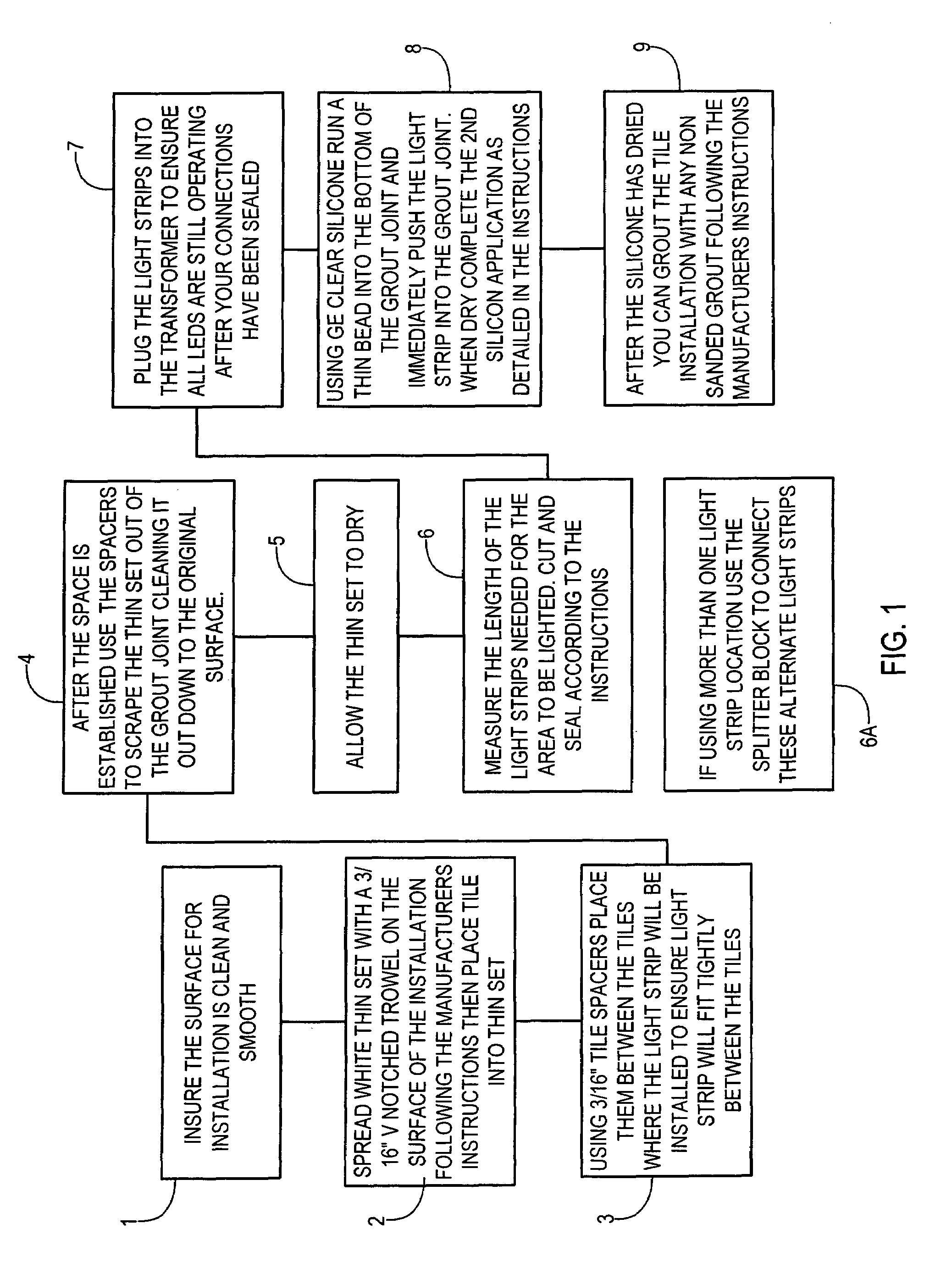
Devices, apparatus, systems, and methods of installing LED (light emitting diodes) for glass tiles and glass blocks. The LEDs can be housed in flexible strips having flexible bendable transparent housing sleeves with ends that can interconnect by male and female ends to one another with various types of interconnectors. Each separate sleeve can house up to 33 LEDs in a transparent plastic sleeve. A transparent connector sleeve can be slid over the interconnected ends and heat shrunk in place. The glass tiles can be laid out to uniform joints spacings between the glass tiles of approximately 3 / 16 of an inch. The LED strips can be placed on a surface layer of transparent grout that has been laid in the joint spacing, followed by a top layer of transparent grout. The transparent grout can be removable grout and include clear Silicon. The LED strips can have peel and stick back layers with adhesive backing that allows mounting to the lower surface. The LED strips can be placed with glass tiles, and other types of tiles such as but not limited to ceramic tiles, stone tiles and the like, as well as with glass blocks. Splitter(s) can be used to run parallel runs of LED strips at different spaced apart locations.

Description

[0001]This invention relates to lighting, in particular to devices, apparatus, systems, and methods of installing LED (light emitting diodes) for glass tiles and glass blocks.BACKGROUND AND PRIOR ART[0002]Glass tiles for walls and floors have become increasingly popular to allow light transmission therethrough and there have been developments to light these tiles to show off their colors. Various types of lighting have included glass bulbs. However, bulbs do not have a long life and removing such bulbs would be expensive and time consuming.[0003]Another way to provide lighting for these tiles is to use fiber optics that are powered by a halogen light sources. However, fiber optic lighting systems are expensive to install and require a lot of energy to light the tiles.[0004]Light emitting diodes (LED's) have been considered in the past as a light source for lighting glass tiles. But it has always required a modification of the basic tile design to receive the LED's. LEDS have been in...

Claims


Application Information

Patent Timeline
Patent Type & Authority Patents(United States)
IPC IPC(8): F21S4/00
CPCF21S4/006F21V23/06F21V33/006H01R31/02F21S2/005E04F2290/026F21Y2101/02H01R4/72H01R13/6392F21S4/24F21Y2103/10F21Y2115/10
Inventor TEETERS, RACHEL
Owner NEW HORIZON DESIGNS
Learn More