Tunneling needle design having an on-demand removable hub

a technology of rotating needles and hubs, which is applied in the field of surgical instruments, can solve the problems of difficult, if not impossible, to thread the catheter, and the design approach is not working, and achieves the effect of reducing the difficulty of removing the stylet or the catheter

Inactive Publication Date: 2009-06-23
VAISMAN JULIEN +1
View PDF5 Cites 2 Cited by
  • Summary
  • Abstract
  • Description
  • Claims
  • Application Information

AI Technical Summary

Benefits of technology

[0021]However, it was Tuohy himself that recognized that the directional point of the Huber needle might facilitate placement of spinal catheters [E. B. Tuohy, Anesthesiology 5:142-148 (1944)]. As a further improvement, Tuohy also added a stylet to the needle design, thereby further decreasing the risk of skin plugging. These marked changes and improvements have caused the combined Tuohy-Huber needle design to become popularly known as the “Tuohy needle”.
[0047]3. This safe needle has a double function : the needle can be used to pierce the desired tissue surface; and, in addition, the needle can also be used as a tunneling device, eliminating the need for an additional tunneling instrument. Cost is reduced.

Problems solved by technology

This technique was essentially the same approach that Aburel had tried several years before, but this effort was far less successful than the first.
Hingson and Southworth obtained satisfactory anesthesia in only 10 of 16 patients; and the placing of the sharp pointed needle in the epidural space, not to mention maintaining the position of the catheter, must have been a major challenge in and of itself.
This design approach did not work.
However, the resulting Touhy-Flowers needle design [see Prior Art FIG. 2C] tended to bend at the tip, making it difficult, if not impossible, to remove the stylet or to thread the catheter.
Unfortunately, the Cheng needle was described as “cumbersome” to use and “extremely difficult to effect” by Cheng's contemporaries; and like many other needle designs, it is not commercially available for use today.
Despite all these innovations and developments in spinal needle design, there remains a well recognized problem and long-standing potential danger when conventional spinal needles are employed as devices for subcutaneous tunneling.
The use of this technique introduces a serious risk of cutting or severing the catheter or wire when the sharp tip is pushed into the incision where the catheter or wire is located.
Additionally, the tunneling of the needle from the exit site towards the surgical incision increases the possibility of bacterial contamination since the needle is being introduced through potentially colonized skin at the remote exit site.

Method used


Image

  • Tunneling needle design having an on-demand removable hub
  • Tunneling needle design having an on-demand removable hub
  • Tunneling needle design having an on-demand removable hub

Examples


first alternative embodiment

A First Alternative Embodiment

[0083]In this first alternative embodiment, only the engagement means disposed at the second open end of the needle body, and the attachment means disposed at one open end of the hub structure differ from those in the preferred embodiment described above. This first alternative embodiment is illustrated by FIGS. 6A and 6B.

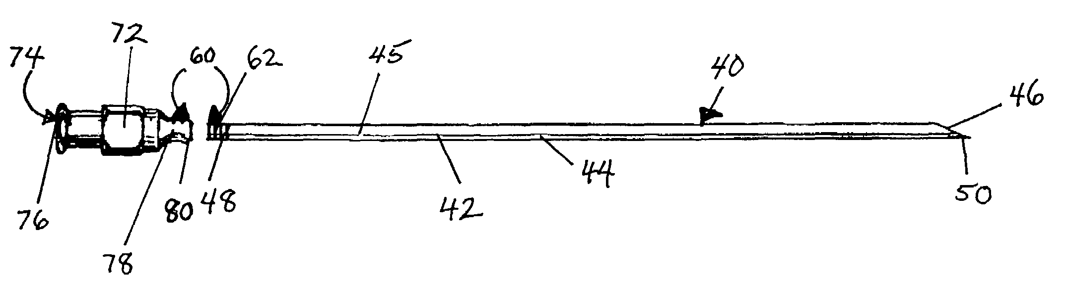
[0084]Thus, as shown by FIGS. 6A and 6B, the needle-hub construct 130 includes an elongated, rigid needle body 140 comprised of: a hollow shaft 142 having fixed dimensions and configuration; at least one solid wall 144 formed of a stiff and unbendable material; an open internal cavity 145; and discrete first and second open ends 146, 148.

[0085]A sharp open tip 150 is formed at and extends from the first open end 146. In addition, discrete engagement means 160 are disposed at and joined to the second open end 148 for at will engagement and disengagement of a needle hub 170.

[0086]The particulars of the engagements means 160 in this first...

second alternative embodiment

A Second Alternative Embodiment

[0094]As before, only the engagement means disposed at the second open end of the needle body, and the attachment means disposed at one open end of the hub structure differ from those in the preferred embodiment described above. The second alternative embodiment is illustrated by FIG. 7.

[0095]As seen in FIG. 7, the needle-hub construct 230 includes an elongated, rigid needle body 240 comprised of: a hollow shaft 242 having fixed dimensions and configuration; at least one solid wall 244 formed of a stiff and unbendable material; an open internal cavity 245 (not shown); and discrete first and second open ends 246, 248.

[0096]A sharp open tip 250 is formed at and extends from the first open end 246. In addition, discrete engagement means 260 are disposed at and joined to the second open end 248 for at will engagement and disengagement of a needle hub 270.

[0097]The particulars of the engagements means 260 in this second alternative embodiment comprise two s...


PUM


Abstract

The present invention provides a medical needle assembly which has a removable at will needle hub for a spinal needle, which can be used to access the epidural or subarachnoid space of the spinal cord. This improvement in spinal needle design allows and facilitates the use of the medical needle for the purposeful creation of a subcutaneous tunnel and the placement of a catheter, or drain, or electrical wire lead which extends to an anatomic location remote from the original surgical incision site.The medical needle assembly has unique features and capabilities: a removable at will needle hub, which not only allows the surgeon to use the epidural / spinal needle initially to access the epidural or subarachnoid space of the spinal cord; but also permits the surgeon to use the same medical needle assembly again as a tunneling instrument. This allows the surgeon to perform the process of subcutaneous tunneling safely and in a manner previously considered to be surgically improbable.

Description

FIELD OF THE INVENTION[0001]The present invention is concerned with surgical instruments employed for percutaneous tunneling from a surgical entry site on the skin which accesses the epidural and / or subarachnoid spaces surrounding the human spinal cord. It is particularly directed to the creation and use of a modified epidural / spinal needle device for safe tunneling through the subcutaenous tissues to externalize a temporary catheter or spinal cord stimulator lead at a location remote to the original surgical incision.BACKGROUND OF THE INVENTION[0002]In the field of pain management and neurosurgery, certain surgical procedures often require the internal placement and passage of tubes or wires from the spine to an external drainage system, a drug infusion system, or an electrical power source. Passage is best made through a subcutaneous tunnel in order to reduce the possibility of local or generalized infection; as well as to provide a secure anchor to the skin in order to avoid disl...

Claims


Application Information

Patent Timeline
Patent Type & Authority Patents(United States)
IPC IPC(8): A61F11/00
CPCA61B17/3401A61B2017/320056A61M25/0097
Inventor VAISMAN, JULIENORDIA, JOE I.
Owner VAISMAN JULIEN
Why Eureka
Try Eureka