Wind turbine and method for the automatic correction of wind vane settings

a technology of automatic correction and wind turbine, applied in the direction of electric generator control, machines/engines, mechanical equipment, etc., can solve the problems of not being able to achieve the optimal rotor alignment on its own, and other types of position errors can be compensated, so as to achieve less complexity and more accurate alignment

Inactive Publication Date: 2009-06-23
SENVION GMBH
View PDF12 Cites 13 Cited by
  • Summary
  • Abstract
  • Description
  • Claims
  • Application Information

AI Technical Summary

Benefits of technology

[0007]The invention is based on the object, against the background of the prior art as cited above, of providing a wind energy installation and a method for alignment of the wind energy installation, which allows more accurate alignment, even in difficult conditions, with little complexity.
[0011]One major aspect is based on the use of a specialized element to form an efficiency measure. The efficiency measure is an indicator of the magnitude of the actual output of the wind energy installation in the given wind conditions, that is to say how well it makes use of the wind. The efficiency measure results in the controller being independent of influences which are caused by changes in the wind speed. Various physical variables may be used as a quantity for the efficiency measure. This will frequently be the electrical power. However, it is also possible to use the electrical energy that is generated. This has the advantage that, when a measurement is carried out over a specific time period, brief fluctuations are compensated for automatically by the integration associated with this. However, other variables can also be used, such as the electrical torque of the generator or the mechanical torque passed from the rotor to the generator, or to an intermediate transmission. The efficiency measure element is preferably in the form of a normalization element, which is designed to normalize the quantity with respect to the wind speed. This is expediently done in the simplest form by forming the ratio of the electrical power to the third power of the wind speed. This makes it possible to eliminate the influence of varying wind speeds. The invention can even take account of those errors which occur as a result of wind direction shifts resulting from a freshening wind. The quality of the azimuth position is therefore considerably improved.
[0013]The efficiency measure element preferably additionally has a system model of the rotor / generator system. The system model includes system knowledge relating to the mechanical and electrical behaviour of the rotor / generator system for conversion of mechanical energy to electrical energy, in the form of a mathematical model. In this case, particular account is also taken of influencing variables such as inertia of the rotor / generator system. A model such as this can be used to improve the quality of the efficiency measure that is formed since even a rotor rotation speed which varies only slowly under the influence of gusts can be recorded appropriately. The model can intrinsically be designed as required. However, it has been found to be advantageous for it to be in the form of a first-order delay element. This allows the system behaviour to be approximated well with comparatively little effort. It is also possible to provide for the system model to map the system behaviour, in terms of different efficiency levels of the wind energy installation. By way of example, the efficiency levels differ in different operating ranges of the wind energy installation. The efficiency level in the region of the optimum tip-speed ratio is higher than in the upper constant rotation speed control range, and is also, once again, different from the efficiency level in the lower power range. A system model configuration such as this makes it possible to refine the mapping of the system behaviour.
[0015]The efficiency measure element is preferably designed to be self-adapting. This makes it possible for it to autonomously match itself to varying location-dependent or wind-condition-dependent factors. This is particularly advantageous when distortion occurs in the case of winds from one specific direction, leading to incorrect measurements of the wind direction via the weathervane, or for which the wind is not homogeneous, when seen over the rotor area. Furthermore, a correction module is expediently provided. This allows adaptation of the wind energy installation overall, or matching different components on it. For example, a wind energy installation may be equipped with different rotor blades, whose blade depths differ. This is also in turn dependent on how severely the rotor blades corrupt the wind measurement via the weathervane on the machine housing. Corresponding correction values can be stored in a module such as this in order to call them up as required as a function of the actual equipment fit of the wind energy installations.
[0018]The measurement device can be designed such that it determines the wind direction in an absolute or relative form. In this case, absolute is understood as being a value related to an Earth-fixed coordinate system (for example clockwise, based on north). Relative means a coordinate system which is related to the azimuth position of the machine housing, with the reference line in this case being the rotor axis. The measurement device is preferably arranged on the machine housing. This has the advantage of a compact and simple arrangement in the vicinity of the corresponding rotor. However, it is quite possible for the measurement device to be arranged separately, for example on a separately installed measurement tower. This variant is particularly appropriate when a plurality of wind energy installations have to be supplied with data from the same measurement device. An indirect wind measurement can also be provided instead of a direct wind measurement as described above. For example, the measurement devices can be designed to record tower bending or rotor-blade bending torques. The latter offers the advantage that it allows a relative measurement, in contrast to the measurement methods mentioned above, which measure the wind strength in an absolute form (using Beaufort, meters per second, knots, etc.). Relative means that the rotor blade bending torques increase particularly markedly when the machine housing is not aligned correctly with the wind. This applies in particular to periodic changes in the rotor-blade bending torques.

Problems solved by technology

However, other types of position error can also be compensated for, for example those caused by poor incidence flow conditions on the weathervane (dynamic errors), such as those which can occur by deflection of the airflow in the lee of the rotor (corkscrew effect).
Even a weathervane which can measure as accurately as this cannot on its own achieve optimum rotor alignment.

Method used


Image

  • Wind turbine and method for the automatic correction of wind vane settings
  • Wind turbine and method for the automatic correction of wind vane settings
  • Wind turbine and method for the automatic correction of wind vane settings

Examples


Embodiment Construction

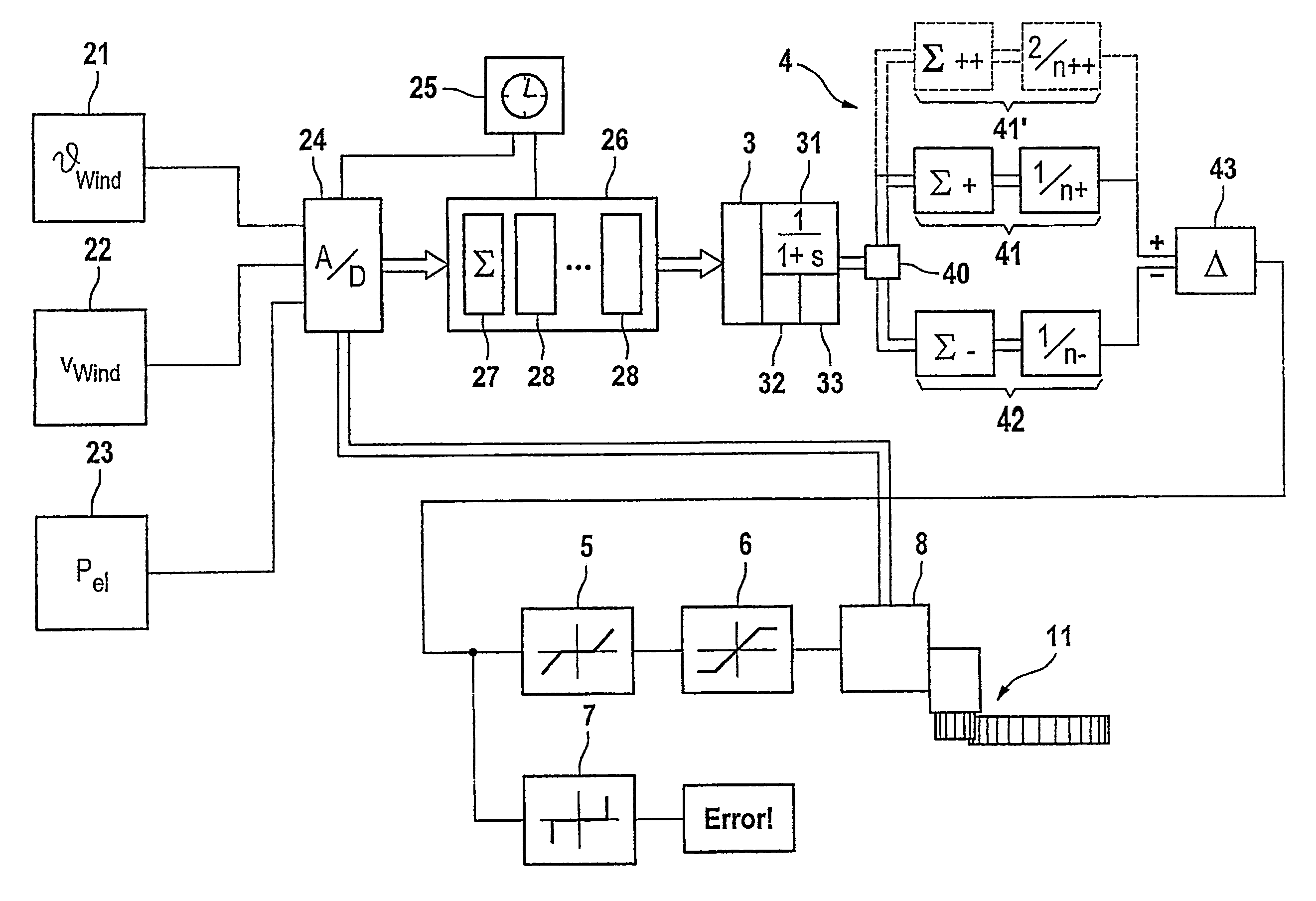
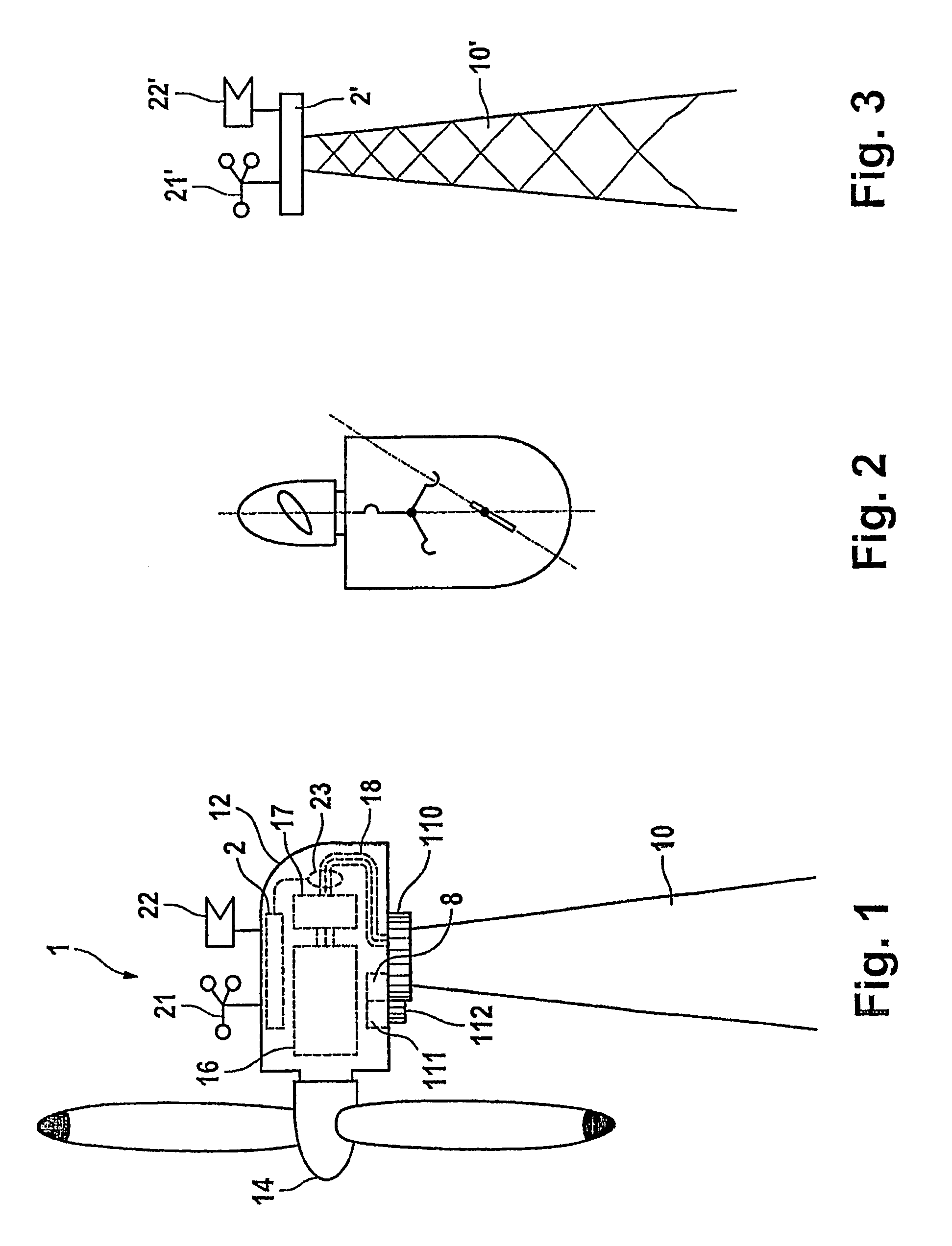
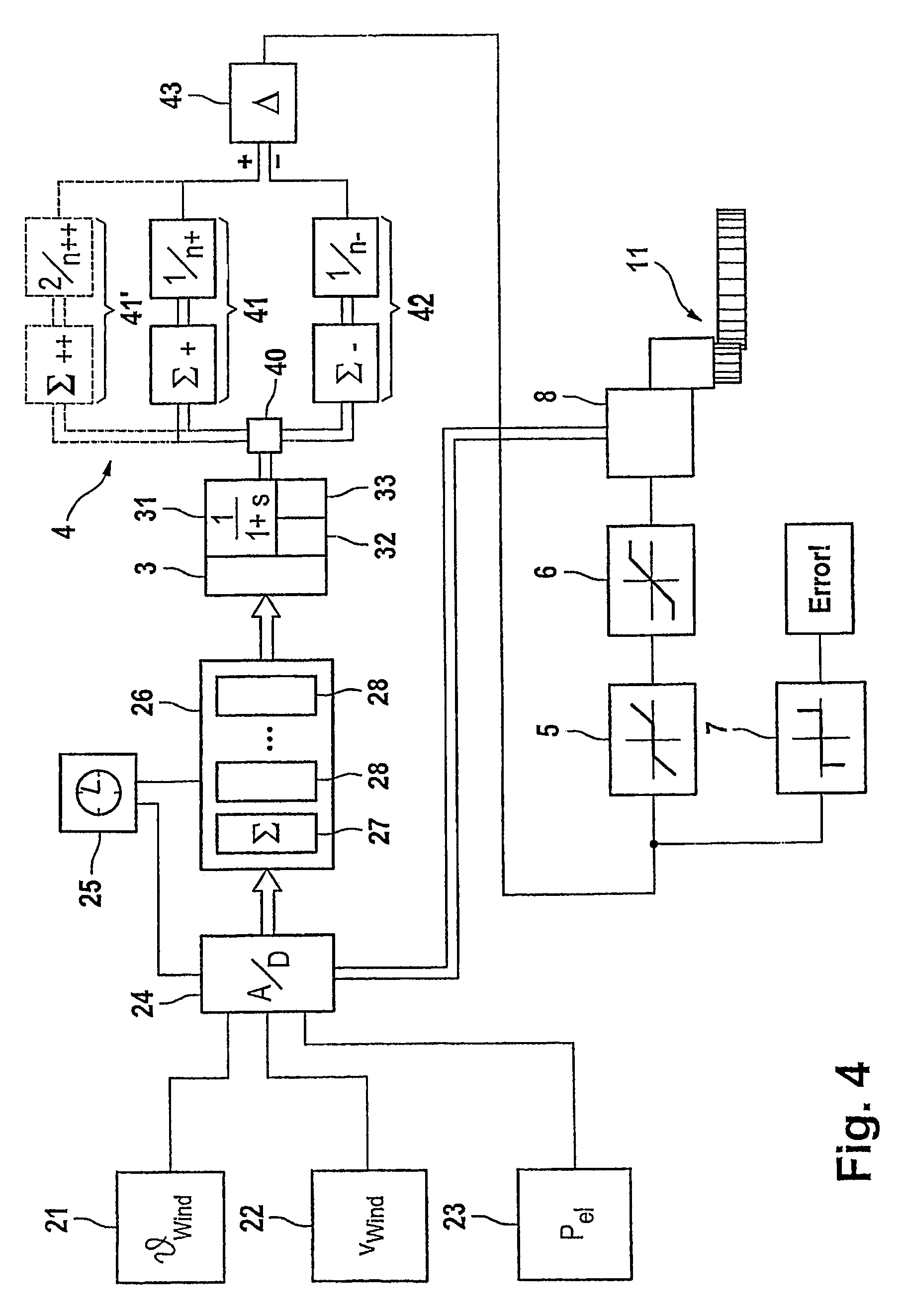
[0034]FIG. 1 shows a wind energy installation according to one exemplary embodiment of the invention, which has a tower as the pylon 10 at whose tip a machine housing 12 is arranged such that it can pivot. A rotor 14 with a plurality of blades is arranged such that it can rotate on one end face of the machine housing 12. This acts by means of a shaft, which is not illustrated, on a generator 16 in order to produce electrical power. Furthermore, a converter 17 and lines 18 are provided in order to pass the electrical power into the tower 10, and from there to the loads. Furthermore, a controller 8 for azimuth adjustment of the machine housing 12 is arranged in the machine housing 12. Sensors 21, 22 for wind parameters (wind strength and wind direction) as well as an electrical power measurement device 23 and a pivoting device 11, as an actuator, interact with this controller 8.

[0035]The mechanical design for azimuth adjustment will be explained first of all. A large circumferential t...


PUM


Abstract

The invention relates to a wind turbine comprising a machine housing (12) equipped with a rotor (14), which is mounted to pivot on a sub-structure (10). Wind parameters and an electromechanical quantity are determined by means of measuring devices (21, 22, 23). To enable the machine housing (12) to track the wind, the wind turbine is equipped with a pivoting device (11) comprising a controller (8). The wind turbine is also equipped with a calibration module (2), which is configured to determine an effective mass of the electromechanical quantity using the wind speed. In addition, the turbine comprises an evaluation device (4) comprising a classifier (40), which is used to form a first average value for a first class, for which the wind direction is positive and a second average value for a second class, for which the wind direction is negative. A difference is determined by means of a comparator and a calibration signal is emitted to the controller (8) of the pivoting device (11). The invention permits an autonomous calibration of the controller (8) for the tracking of the machine housing (12) and thus reduces the risk of an erroneous positioning of the rotor (14) in relation to the wind direction, irrespective of the prevailing wind conditions. The invention is particularly stable in relation to variable wind forces and directions, especially in the presence of gusts.

Description

REFERENCE TO RELATED APPLICATIONS[0001]This application is a national stage application under 35 USC 371 of International Application No. PCT / EP2005 / 011352, filed Oct. 21, 2005, which claims the priority of German Application No. 10 2004 051 843.2, filed Oct. 25, 2004, the contents of both of which prior applications are incorporated herein by reference.FIELD OF THE INVENTION[0002]The invention relates to a wind energy installation having a pylon, having a machine housing which is arranged on the pylon and whose azimuth position can be adjusted by means of a pivoting device, to a rotor which is arranged on one end face of the machine housing, such that it can rotate and drives a generator for production of electrical power, and to a controller for the pivoting device, to which measurement devices are connected in order to measure wind parameters and an electromechanical quantity.BACKGROUND OF THE INVENTION[0003]Modern wind energy installations are provided with rotors which have to ...

Claims


Application Information

Patent Timeline
Patent Type & Authority Patents(United States)
IPC IPC(8): F03D7/00
CPCF03D7/0204F03D7/042F05B2270/32F05B2270/321F05B2270/802Y02E10/723F05B2270/335Y02E10/72
Inventor ALTEMARK, JENS
Owner SENVION GMBH
Why Eureka
Try Eureka