
Image pickup apparatus for clamping optical black level to a predetermined level

a predetermined level and image pickup technology, applied in the field of image pickup technology, can solve the problems of large fluctuation (frequency of fluctuation) per clamping operation, uneven offset error in each imaging device, and easy noise in the shape of horizontal stripes, so as to prevent blacking of images and high speed

Inactive Publication Date: 2009-06-23
CANON KK
View PDF13 Cites 15 Cited by
  • Summary
  • Abstract
  • Description
  • Claims
  • Application Information

AI Technical Summary

Benefits of technology

The present invention is about an image pickup apparatus that can prevent the image from being affected by blooming and quickly restore it to its original state. The apparatus includes an optical black level extraction unit, a blanking level extraction unit, an abnormality detection unit, and a clamp unit. The clamp unit can adjust the optical black level based on the optical black level extraction unit or the blanking level extraction unit, depending on whether there is an abnormality detected or not. This invention can improve the quality of images captured by the image pickup apparatus.

Problems solved by technology

The offset error is uneven in each imaging device and fluctuates depending on the temperature.
However, along with that, the amount of fluctuation (frequency of fluctuation) per clamping operation also becomes larger.
As a result, a noise in the shape of horizontal stripe can easily occur.
In the conventional feedback OB clamp circuit like this, the offset error caused by a CCD offset component and a dark current component of the imaging device are considered to be the main cause of the amount of fluctuation of OB.
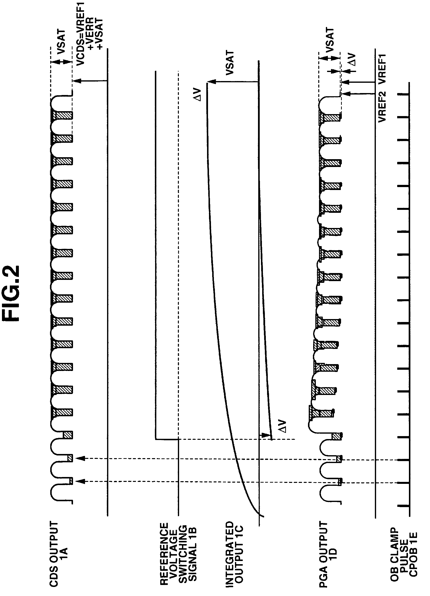
Thus, in the configuration of the conventional clamp circuit, there has been a problem in that the image signal follows up the inaccurate black level which deviates substantially from the appropriate OB level when the blooming occurs and that the whole image signal is subject to blacking.
In addition, as a result of following up to the inaccurate black level deviating substantially from the appropriate OB level, it takes very long to return to the normal OB level after the blooming of the imaging device has been cancelled and the blacking continues during the restoration time.

Method used


Image

  • Image pickup apparatus for clamping optical black level to a predetermined level
  • Image pickup apparatus for clamping optical black level to a predetermined level
  • Image pickup apparatus for clamping optical black level to a predetermined level

Examples


first embodiment

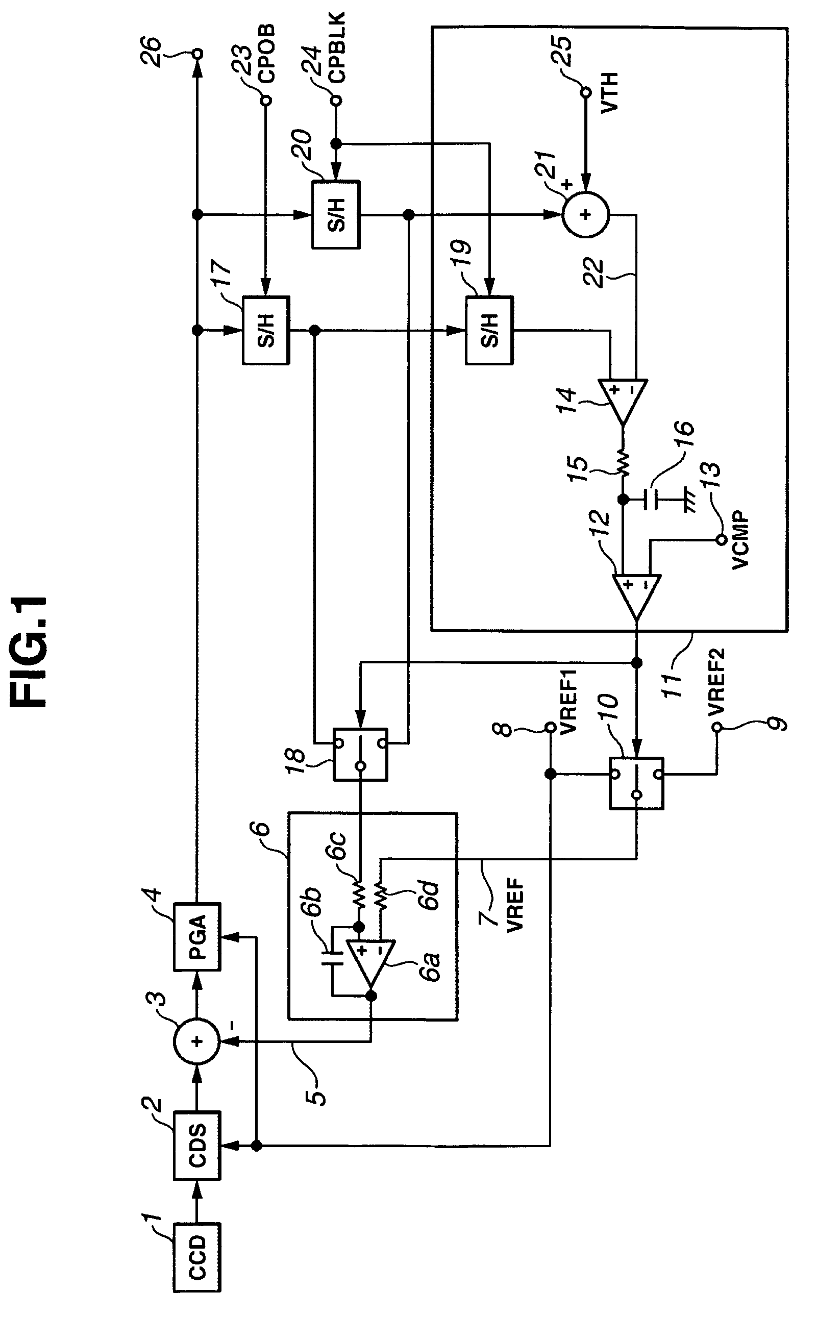
[0043]FIG. 1 is a block diagram showing an example of a configuration of a feedback OB clamp circuit according to a first embodiment of the present invention.

[0044]First, the configuration of FIG. 1 is explained. Reference numeral 1 denotes a CCD (CCD image sensor: an imaging device) for converting an optical image of an object into an electrical signal. After the image signal outputted from the CCD 1 is inputted to a circuit 2 called CDS (correlated double sampling) and a reset noise is removed there from, the image signal is inputted to an offset adder circuit 3 and a predetermined offset (direct current) voltage is added to the image signal, and then an offset addition result is inputted to a variable amplifier 4. The variable amplifier 4 amplifies the image signal by a predetermined gain or a variable gain.

[0045]The CDS circuit 2 constitutes a CDS circuit which has a predetermined reference voltage VREF1 inputted by a terminal 8 as a reference of a feed-through part of the image...

second embodiment

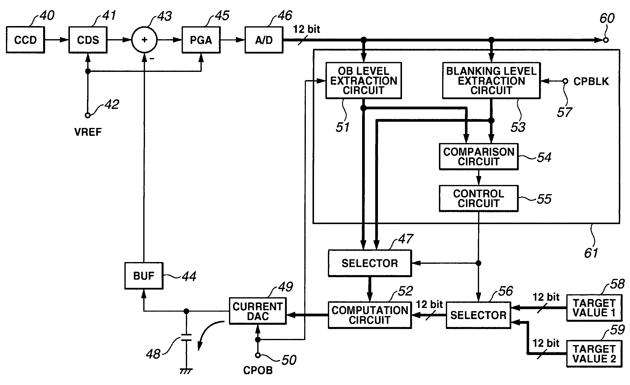
[0089]The feedback OB clamp circuit shown in the first embodiment is configured to feed back the output signal of the variable amplifier. In this regard, while image pickup equipments are recently digitalized, the A / D converter is often and generally provided in the post-stage of the variable amplifier and utilized to feed back the digital output thereof.

[0090]The configuration and operation according to the second embodiment of the present invention are arranged so that, also in relation to a digital feedback OB clamp circuit, the blacking due to fluctuation in the OB level at the time of occurrence of the blooming can be suppressed and the clamp restoration time to the normal OB level after the cancellation of the blooming can be shortened.

[0091]FIG. 4 is a block diagram showing an example of the second embodiment of the present invention.

[0092]The configuration of FIG. 4 is explained below. Reference numeral 40 denotes a CCD (CCD image sensor) for converting the optical image of ...


PUM


Abstract

An image pickup apparatus includes an imaging device configured to convert an optical image of an object into an electrical signal, an optical black level extraction unit configured to extract an optical black level included in an image signal obtained by photoelectric conversion by the imaging device, a blanking level extraction unit configured to extract a blanking level in a blanking period of the image signal, an abnormality detection unit configured to detect an abnormality of the optical black level, and a clamp unit configured, at a normal time when the abnormality is not detected by the abnormality detection unit, to clamp the optical black level to a first target value with the optical black level extracted by the optical black level extraction unit as a reference, and at an abnormal time when the abnormality is detected by the abnormality detection unit, to clamp the optical black level to a second target value with the blanking level extracted by the blanking level extraction unit as a reference.

Description

BACKGROUND OF THE INVENTION[0001]1. Field of the Invention[0002]The present invention relates to an image pickup technology, and more particularly to an image pickup apparatus and an image pickup method for clamping an optical black level to a predetermined level.[0003]2. Description of the Related Art[0004]Conventionally, in displaying and recording a still image and a motion picture picked up by a solid-state imaging device such as a CCD, an optical black (hereafter referred to as OB) level of the imaging device is utilized as a reference of luminance level of an image signal. OB refers to a pixel output shaded within a photo detection pixel portion of the imaging device and not dependant on an incident light.[0005]One example of a device configuration of a feedback clamp DC component recovery (clamp) circuit using the OB level as a black reference of the image signal, which is commonly utilized in a video camera and the like, is shown in FIG. 7. A main operating waveform thereof ...

Claims


Application Information

Patent Timeline
Patent Type & Authority Patents(United States)
IPC IPC(8): H04N9/64H04N5/217H04N23/40H04N5/18H04N25/00
CPCH04N5/3575H04N5/3591H04N5/361H04N5/3658H04N25/621H04N25/616H04N25/677H04N25/633H04N25/63
Inventor ISE, MAKOTO
Owner CANON KK
Learn More