Lying surface for a bed, in particular a healthcare and/or hospital bed

a technology for laying surfaces and beds, which is applied in the direction of bedsofas, tables, physical therapy, etc., can solve the problems of irritating and disturbing, the noise generated by pneumatic and electromotive actuators is not substantial, and the noise is not small. , to achieve the effect of small nois

Inactive Publication Date: 2009-06-30
VOLKER GMBH
View PDF14 Cites 8 Cited by
  • Summary
  • Abstract
  • Description
  • Claims
  • Application Information

AI Technical Summary

Benefits of technology

[0007]It is an object of the present invention to provide a lying surface for a bed, especially a healthcare and / or hospital bed, wherein the lifting units for lifting and lowering at least some of the support elements of the lying surface generate as little noise as possible that advantageously is below the level of normal ambient noise.
[0016]As provided by the invention, the up and down movement of the lifting member or by the lifting member, respectively, is effected through a rotary movement of 360°. Thus, the rotary movement of the lifting member is not inverted for the lifting or lowering movement. The drive motor always rotates in one and the same sense of rotation, whereby it is avoided to repeatedly brake the motor and accelerate it again in the opposite sense of rotation to perform both movements of the lifting member. This in turn reduces noise since the development or generation of noise caused by braking and accelerating the motor can be avoided. Moving the support element(s) of the lying surface up and down may be realized in various different ways. With a view to driving the electromotor, it is somewhat complex to make the lifting member move in opposite directions to perform the lifting and lowering movement. In this respect it is advantageous if the lifting member performs both movements while the drive shaft of the electromotor always rotates in the same sense of rotation. This means in turn that the lifting member is configured as a part of a crank drive or as an element controlled by a slotted link or a cam track. To perform a lifting movement, a crank drive requires substantial force transmission in at least two rotational positions of the crank. In view of this, a rotatory element with a cam track control seems suitable as a lifting member. The rotatable lifting member is provided with a radially or axially projecting cam adapted to be moved under control in a slotted link or along a cam track as the lifting member rotates. A configuration of a rotationally driven lifting member with cam track control results in one lifting and lowering movement through a 360° rotation. For the electromotor to carry out the necessary stroke with the required force at minimum power, which, in first approximation, results in not too much noise being generated by the motor, it is suitable that the lifting member performs the lifting movement through as large a rotational angle range as possible. Thus, it is suitable in this respect if the upward movement is carried out through more than 180° of the rotary movement of the lifting member and, in particular, is carried out through 270° or more than 270°. It is not disadvantageous for the downward movement of the lifting member or the support element, respectively, if it is carried out through a substantially smaller rotational angle range compared to the upward movement, which, for example, covers only 90° in the latter case mentioned above.
[0017]Instead of a cam, a cam track controlled lifting member may also have a beveled front end abutting a counter bevel surface beveled under the same angle. When the lifting member thus configured is rotated about a rotational axis extending through the front end side with respect to the (stationary) counter bevel surface, the two bevel surfaces alternately move apart and towards each other. Here, the beveled front end side of the lifting member performs a tumbling movement. To reduce wear on the contacting beveled surfaces, it is advantageous to rotatably support a ring element either at the front end side of the lifting element or at the counter bevel surface, the ring element being in contact with the opposite bevel surface. This ring element is supported for rotation about a rotational axis extending vertically to the bevel surface at which the ring element is provided. Thus, the ring element rolls on the bevel surface opposite thereto when both are rotated relative to each other. Preferably, the rotatable support of the ring element is obtained by a roller bearing. The rolling movement occurring in the lifting member is relatively noise-free which has an advantageous effect on the overall noise generation of the lifting unit.
[0018]In an advantageous development of the invention, it is further provided that the lifting member comprises a disc element oriented under an acute angle with the rotational axis of the lifting member and supported at a counter bevel of the lifting member, the disc element and the counter bevel being oriented under the same acute angle with the rotational axis of the lifting member. In this embodiment of the lifting member, the same has a shaft divided along a plane oblique to the longitudinal axis of the shaft. One part of the lifting member shaft is stationary, whereas the other part of the haft may be rotated about its longitudinal axis. Thus, the rotatable part of the shaft moves away from the stationary part of the shaft during its rotation through 360° (through the first partial rotation in the range between 180° and 270°) to then move back towards the stationary shaft (during the second half of the rotation). In doing so, the bevel surface of the rotatable shaft part rolls on the bevel surface of the stationary shaft part. In order to avoid wear or to reduce friction, this can be improved by providing the disc element with a rotatably supported outer ring element that, when the disc element is rotated, rolls on the counter bevel relative thereto.
[0019]To influence the rotational angle range through which the rotatable shaft part moves away from the stationary shaft part, it is advantageous to arrange the disc element eccentrically with respect to the rotational axis of the rotating shaft part. The disc element with its rotatably supported outer ring element may be supported both at the stationary shaft part and the rotatable shaft part. This always has the same effect on the cinematic of the lifting member. The rotatable support of the outer ring element, which is supported at the opposite bevel surface and rolls thereon, is also advantageous in reducing noise.
[0026]Another contribution to the reduction of noise is achieved by a corresponding selection of the materials of the individual components that move on each other or mesh with each other. Possible material combinations are PA, POM, steel and brass. This is true, for example, for the materials moving on each other in a cam track controlled embodiment of the lifting member. Further, it is advantageous to configure the housing such that it cannot act as a resonant body. In this respect, one requirement is a small volume within the housing. In other words, the housing should enclose the electromotor, the transmission, and possible other elements, such as electronic controls or the like, as closely as possible. For structural reasons, a non-reverberant configuration of the housing can be realized that reduces the transmission of sound to the outside.

Problems solved by technology

The basic problem of the use of actuators to generate local lifting movements within a lying surface of a bed is the rather substantial noise produced by such systems.
Both pneumatic and electromotive actuators generate noise when in operation, which may be perceived by the patients or the persons to be cared for as irritating and disturbing.

Method used


Image

  • Lying surface for a bed, in particular a healthcare and/or hospital bed
  • Lying surface for a bed, in particular a healthcare and/or hospital bed
  • Lying surface for a bed, in particular a healthcare and/or hospital bed

Examples


Embodiment Construction

with reference to an embodiment thereof and to the accompanying drawings. In the Figures:

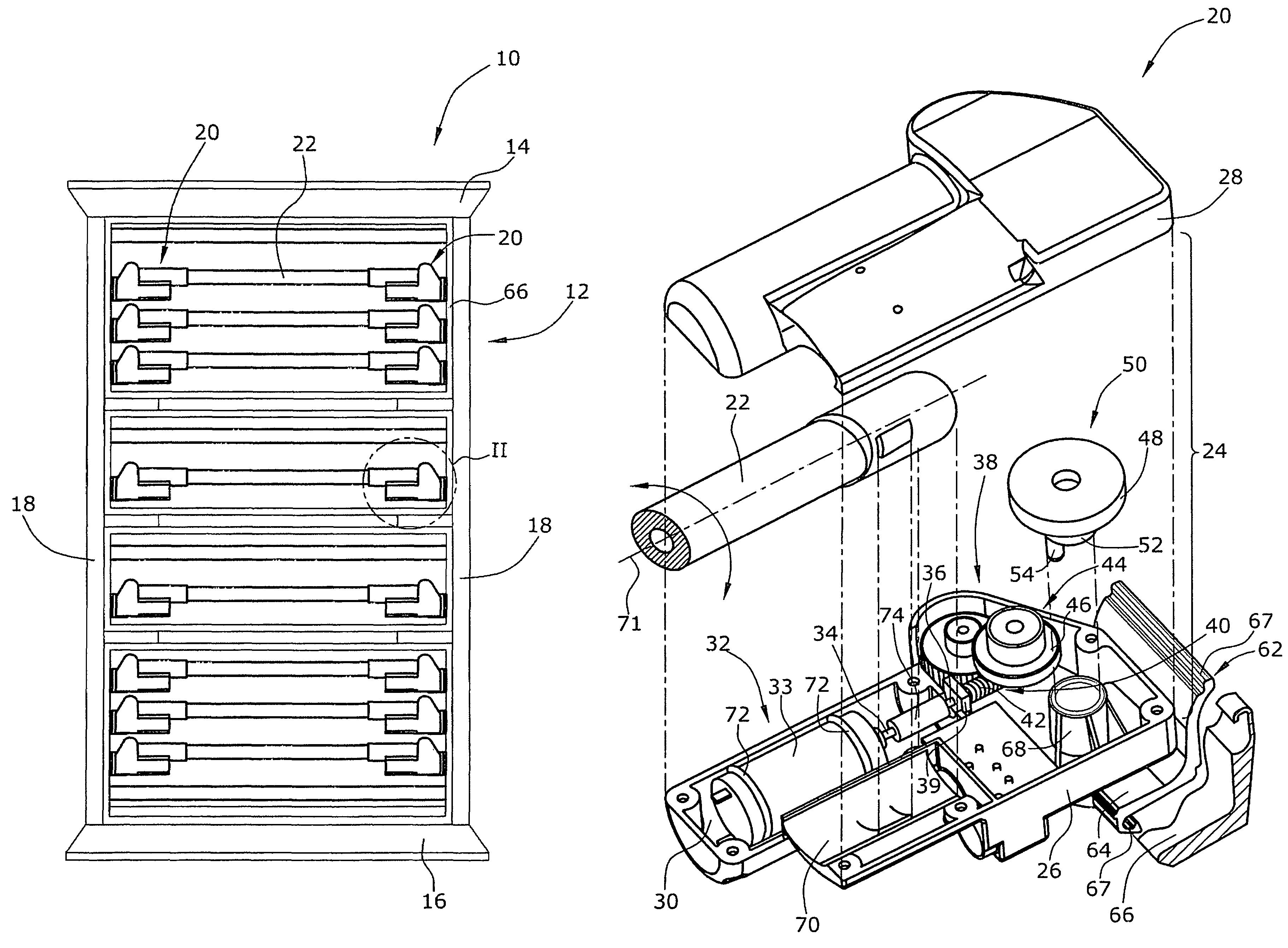
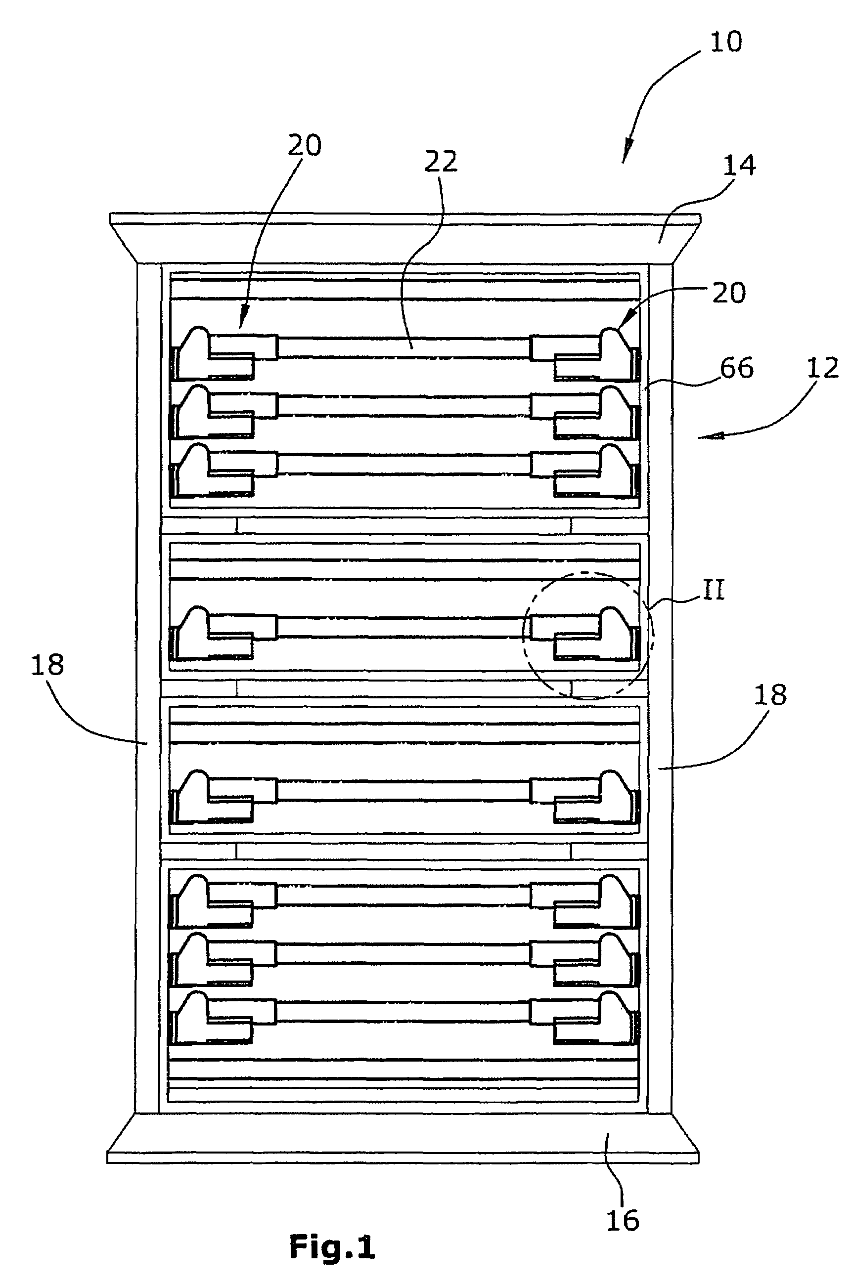
[0031]FIG. 1 is a top plan view of a lying surface of a hospital or healthcare bed with the mattress omitted for clarity,

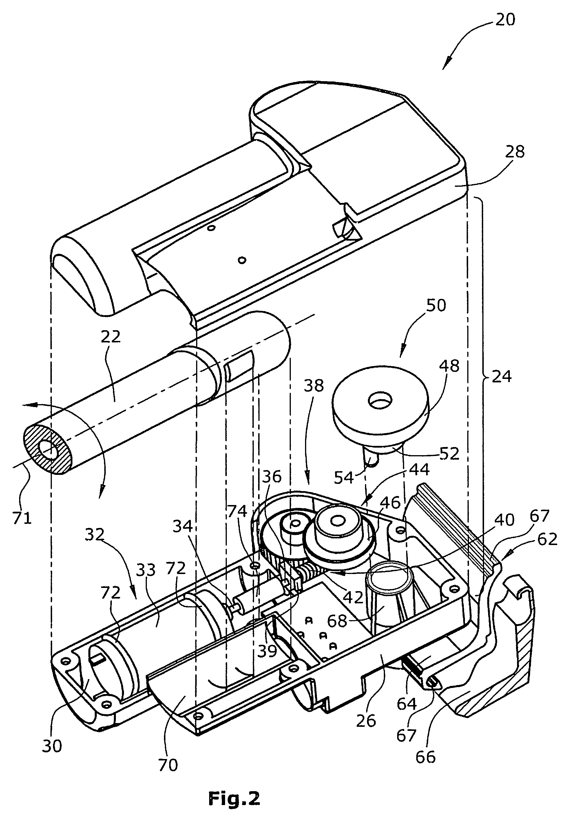
[0032]FIG. 2 is a perspective exploded view of a lifting unit and the coupling thereof to the frame structure of the lying surface,

[0033]FIG. 3 is a perspective view of a detail of the lifting member and the bearing element at which the lifting member is supported,

[0034]FIG. 4 is a top plan view of the bearing element of FIG. 3,

[0035]FIG. 5 is s section through the bearing element along line V-V in FIG. 4,

[0036]FIGS. 6 and 7 are sections along line V-V in FIG. 4, but through an alternative bearing element and lifting member, FIG. 6 showing the situation at minimum stroke and FIG. 7 showing the situation at maximum stroke,

[0037]FIGS. 8 and 9 are sections along line V-V in FIG. 4, but through another alternative bearing element and lifting member, FIG. 8 showing the situation at...


PUM


Abstract

A lying surface for a bed, especially for a healthcare and / or hospital bed, comprises support elements (22) and at least one electro-mechanic lifting unit (20) for lifting and lowering one of the support elements (22) relative to a bearing element (62) of the support element (22). The at least one lifting unit (20) comprises a housing (24) with an electromotor (32) having a drive shaft (34), a transmission (38) and a lifting member (50) supported at the bearing element (62) of said one support element (22). The lifting member (50) is adapted to be rotated by the transmission (38) and to be moved both up and down during a rotary movement of 360°.

Description

BACKGROUND OF THE INVENTION[0001]1. Field of the Invention[0002]The invention is directed to a lying surface for a bed, in particular a healthcare and / or hospital bed.[0003]It is generally known to provide a decubitus prophylaxis in particular to long-term hospital or healthcare patients. Here, a stimulation and a partial pressure relief of the body to be treated is obtained by local minimal movements of the lying surface. Clinical studies have proven the medicinal efficiency of such systems.[0004]2. Description of Related Art[0005]For decubitus prophylaxis and for pain therapy, prior art knows special pneumatic mattresses. Further, for example from WO-A-03 / 028511, an underspringing for mattresses is known, i.e. a mattress support surface with mattress supporting bars extending transverse to the length of the bed, at least several of which are adapted to be purposefully moved up and down pneumatically. Similar systems with fluid-controlled actuators (i.e. pneumatically or hydraulica...

Claims


Application Information

Patent Timeline
Patent Type & Authority Patents(United States)
IPC IPC(8): A61G7/057
CPCA47C23/062A61G7/0573A47C23/067Y10S5/934
Inventor VOELKER, HEINRICH
Owner VOLKER GMBH
Why Eureka
Try Eureka