
Valve connector

a valve connector and connector technology, applied in the direction of functional valve types, couplings, transportation and packaging, etc., can solve the problems of unstable operation of the valve body, inability to maintain certain pressure-flow characteristics of the valve connector, etc., and achieve the effect of long traveling distan

Active Publication Date: 2009-06-30
SUMITOMO RIKO CO LTD
View PDF8 Cites 5 Cited by
  • Summary
  • Abstract
  • Description
  • Claims
  • Application Information

AI Technical Summary

Benefits of technology

The present invention provides a novel valve connector with an internal valve that can secure stable pressure-flow characteristics and prevent the valve body from tilting during traveling. The connector includes a housing with a through-path and an internal valve that can open and close the through-path. The internal valve has a valve seat surface and a valve body with a closing portion that abuts the valve seat surface. A compression spring is biased towards the valve body and holds it always in the correct state. The valve body has guides that allow it to move in the axial direction. The guides have a support recess and a spring bearing that secure the other axial end of the compression spring. The valve body also has a radially inward portion that enters inside the cylindrical portion of the valve cap, preventing the spring from coming out of the support recess. The valve connector ensures stable pressure-flow characteristics and prevents the valve body from tilting during traveling.

Problems solved by technology

However, as there is a tendency to restrict strictly transpiration of a fuel from a fuel supply system, a resin tube is also used instead of the rubber hose.
However, in such structure for supporting the compression spring, when the valve body moves or slides toward the spring bearing while compressing the compression spring, if a shocking vibration happens to act on the valve body, and thereby the valve body slides back toward the valve seat surface for a moment, the one axial end portion of the compression spring, for example, a part of the one axial end portion of the compression spring may come out of the support recess, and may be then caught in the other axial end portion of the guide.
In this state, as a spring force of the compression spring is exerted to the valve body at an angle with respect to the axis, operation of the valve body becomes unstable, and as a result, certain pressure-flow characteristics of the valve connector cannot be maintained.

Method used


Image

  • Valve connector
  • Valve connector
  • Valve connector

Examples


Embodiment Construction

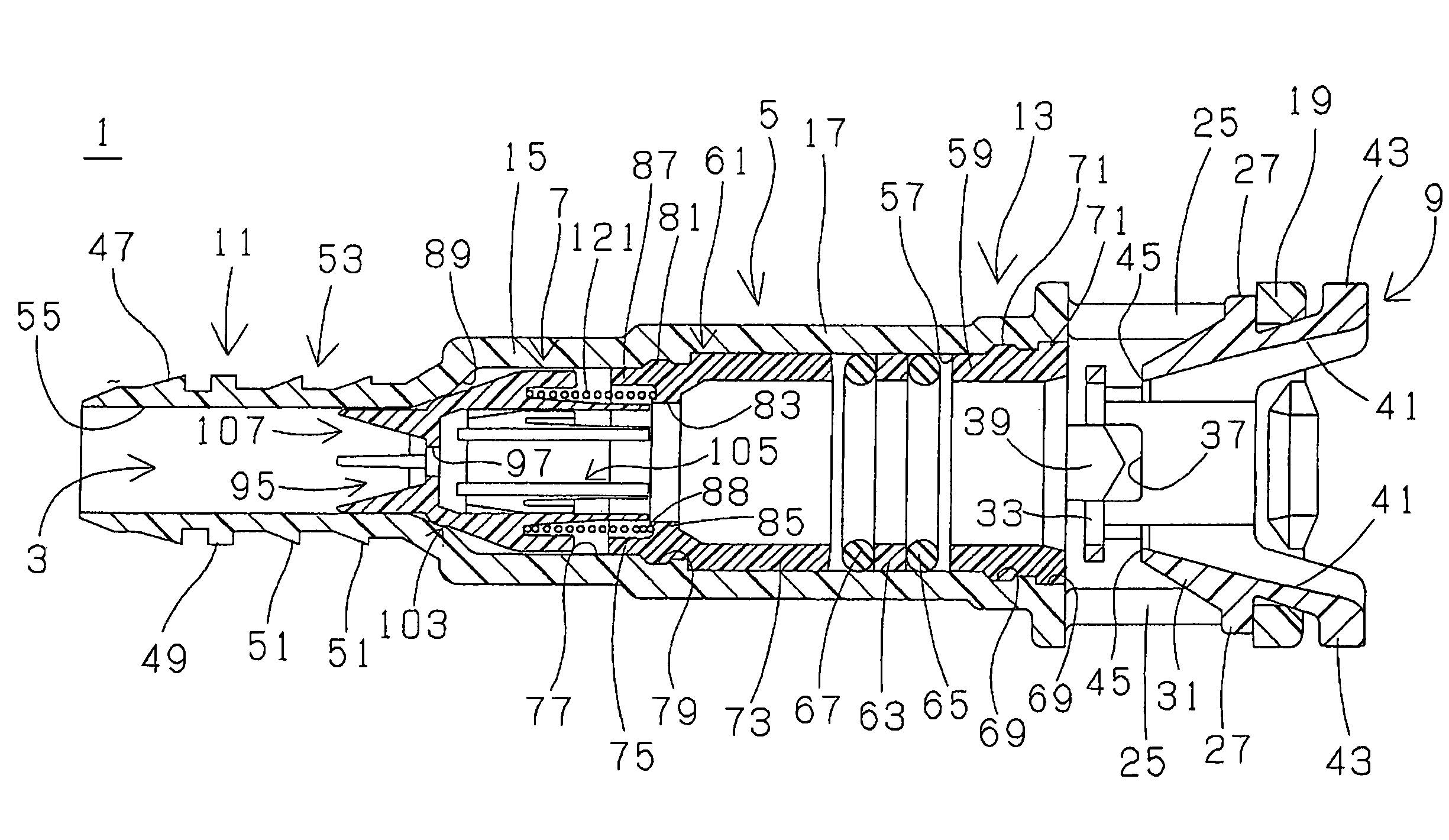
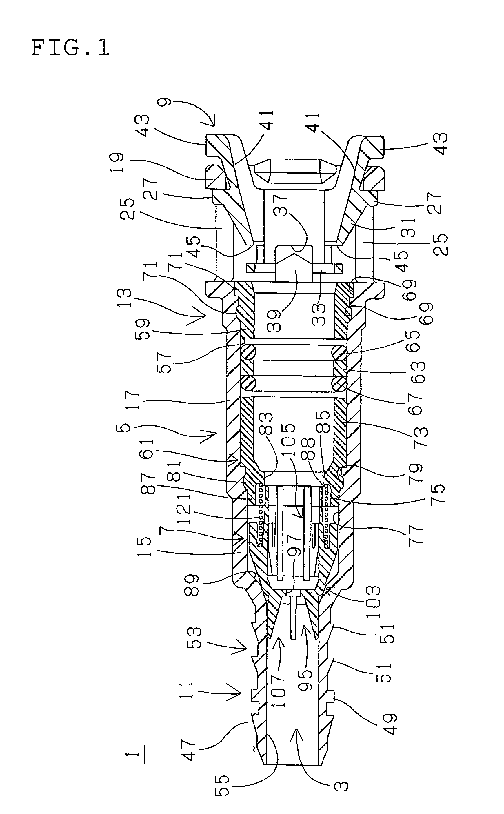
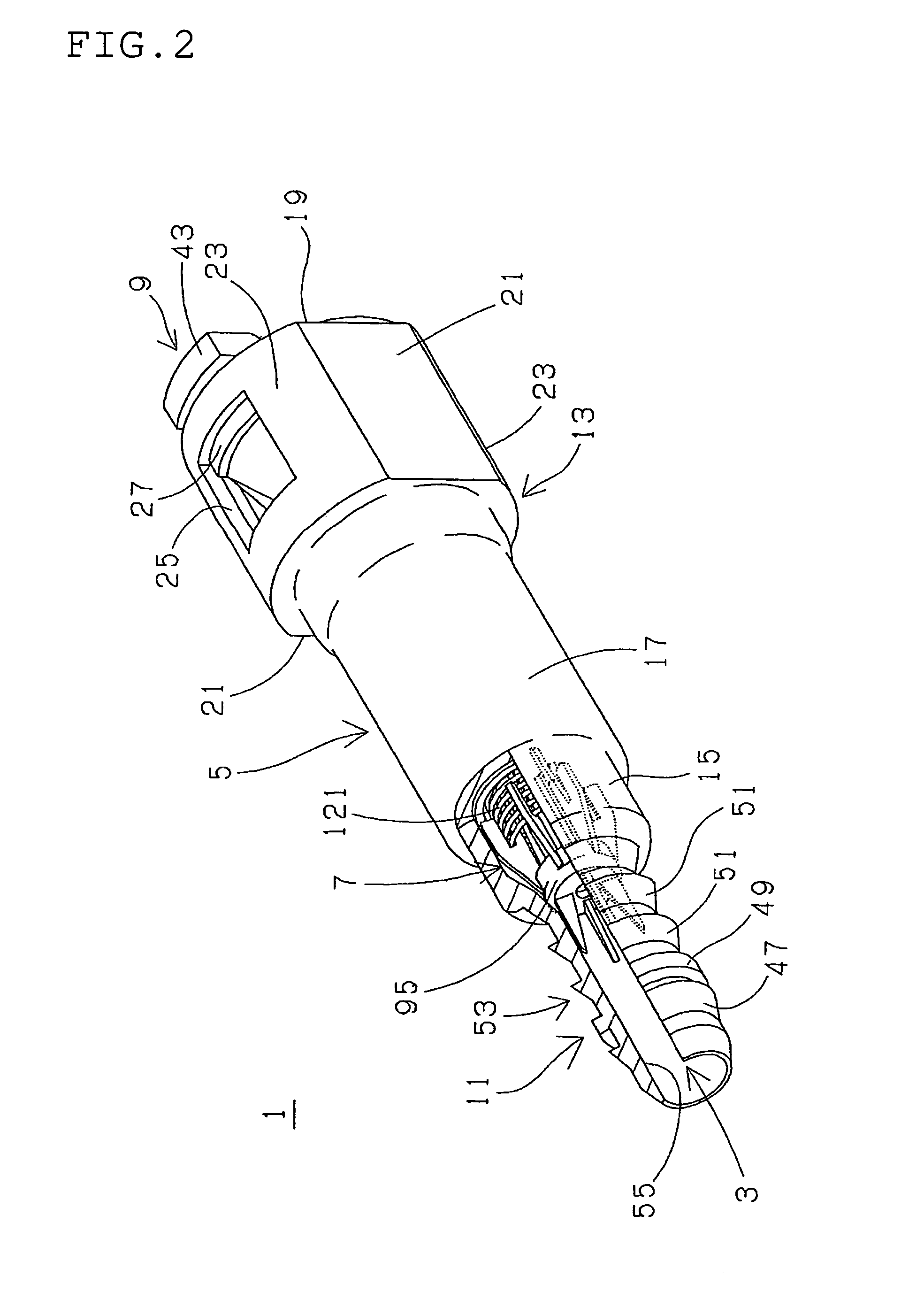
[0026]A valve connector 1 as shown in FIGS. 1 and 2 is used, for example, for evaporation piping or vapor return piping of a tank of fuel such as gasoline, etc., to control flow of a vapor. The valve connector 1 comprises a connector housing 5 having a through-path 3 in an axial direction, an internal check valve 7 fitted and incorporated in the connector housing 5, and a retainer 9 fitted to the connector housing 5. The connector housing 5 is made of glass fiber reinforced polyamide (PA / GF), for example, glass fiber reinforced nylon 6. The retainer is made of polyamide (PA), for example, nylon 12. The connector housing 5 integrally has a tube connecting portion 11 of a small diameter on one axial end thereof, a pipe inserting portion 13 on the other axial end thereof, and a valve housing 15 between the tube connecting portion 11 and the pipe inserting portion 13. The pipe inserting portion 13 integrally includes a pipe support portion 17 on one axial end thereof, and a retainer hol...


PUM


Abstract

A valve connector has a connector housing with a through-path and an internal valve disposed in the connector housing for opening and closing the through-path. The internal valve has a valve body with a plurality of guides. Each of the guides is provided with a support recess for receiving an axial end portion of a compression spring. A radially inward portion on a radially inward end of the guide with respect to the support recess extends longer than a radially outward portion on a radially outward end of the guide with respect to the support recess.

Description

BACKGROUND OF THE INVENTION[0001]1. Field of the Invention[0002]The present invention relates to a valve connector to be used, for example, for controlling a fuel evaporating gas (vapor) in piping such as evaporation piping or vapor return piping in a fuel supply system of a motor vehicle.[0003]2. Description of the Related Art[0004]In order to prevent fuel vapor gas generated in a fuel tank of a motor vehicle from being discharged into an atmosphere, a vapor discharge prevention mechanism that causes the vapor to be adsorbed in a canister has been widely employed. In this type of vapor discharge prevention mechanism, evaporation piping connecting a fuel tank and the canister uses a one-way valve or a check valve to maintain an appropriate pressure in the fuel tank by controlling a flow of the vapor. And, in the vapor discharge prevention mechanism, around a mouth of an inlet pipe and the fuel tank is connected by means of vapor return piping, a part of the vapor in the fuel tank is...

Claims


Application Information

Patent Timeline
Patent Type & Authority Patents(United States)
IPC IPC(8): F16K15/02
CPCF16L37/40Y10T137/7939Y10T137/7929
Inventor NISHIYAMA, TAKAHIRONIKI, NOBUAKI
Owner SUMITOMO RIKO CO LTD
Learn More