Nanotube forming methods

a technology of nanotubes and forming methods, applied in the direction of carbonsing rags, coatings, chemistry apparatus and processes, etc., can solve the problems of difficult sorting nanotubes according to their electrical properties and/or controlling fabrication methods, etc., to achieve effective conductivity, effective conductivity, effective conductivity

Inactive Publication Date: 2009-06-30
MICRON TECH INC
View PDF4 Cites 28 Cited by
  • Summary
  • Abstract
  • Description
  • Claims
  • Application Information

AI Technical Summary

Problems solved by technology

The difficulty in sorting nanotubes according to their electrical properties and / or controlling fabrication methods to produce selected electrical properties remains a major challenge in producing nanotubes and in using nanotubes in certain applications.

Method used


Image

  • Nanotube forming methods
  • Nanotube forming methods
  • Nanotube forming methods

Examples


Embodiment Construction

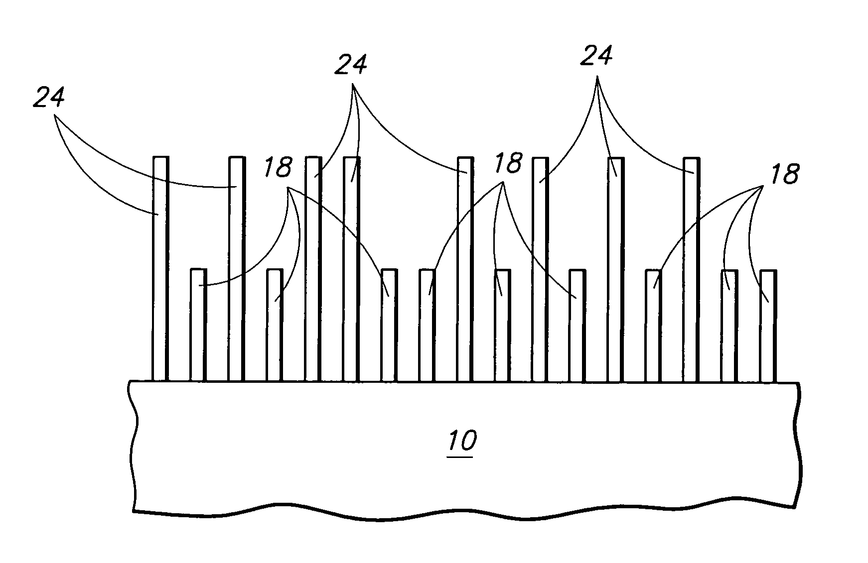
[0023]FIG. 9 shows a chart of single-wall carbon nanotube (SW-CNT) band gap with respect to inverse nanotube diameter. Ecmin is the minimum energy of the conduction band and Evmax is the maximum energy of the valence band. The band gap values in FIG. 9 are based upon tight binding calculations and yield a band gap range of from about 0.3 to about 0.9 electron volts (eV) for respective diameters of from about 50 to about 6 Angstroms. Generally, materials exhibiting a band gap of from about 0.5 to 1.0 eV may be most suitable for a semiconductive channel. Materials that do not exhibit a band gap may be considered conductive (for example, metallic nanotubes). Semiconductive materials exhibiting a band gap less than about 0.01 eV may be considered quasimetallic. Based upon the calculations shown in FIG. 9 for (7,12) chiral SW-CNT, tubes with diameters greater than about 27 Angstroms exhibit a band gap less than 0.5 eV and are less suitable for a semiconductive channel. (According to the ...


PUM

PropertyMeasurementUnit
band gapaaaaaaaaaa
diametersaaaaaaaaaa
band gapaaaaaaaaaa

Abstract

A nanotube forming method includes growing a plurality of nanotubes to an intermediate length that is deterministic of nanotube intrinsic conductivity. Individual nanotubes exhibit an effective conductivity, which varies among the plurality of nanotubes. The method includes completing growth of nanotubes exhibiting effective conductivities inside a selected range without completing growth of nanotubes exhibiting effective conductivities outside the selected range. Before completing nanotube growth, the method may further include stopping nanotube growth and screening out nanotubes exhibiting conductivities outside the selected range. The screening out of nanotubes may include deforming or masking nanotubes exhibiting conductivities outside the selected range. Deforming nanotubes may include applying a potential.

Description

TECHNICAL FIELD[0001]The invention pertains to nanotube forming methods, including but not limited to methods using nanotube screening.BACKGROUND OF THE INVENTION[0002]Nanotubes are well known structures exhibiting useful structural, electrical, thermal, and other properties presently of interest in a wide variety of technology areas. Nanotubes may exhibit a variety of intrinsic conductivity states. Most fabrication techniques used to grow or deposit nanotubes produce a mixture of single-wall nanotubes (SW-NT) and multiwall nanotubes (MW-NT). Fabrication techniques may also produce nanotubes of varying diameter. Further, fabrication techniques may produce a variety of chiralities (zigzag, armchair, and chiral). In addition to their composition and perhaps other physical properties, the listed characteristics can influence whether a nanotube is “metallic” (that is, conductive), semiconductive, or insulative. For single-wall carbon nanotubes, armchair varieties are typically metallic,...

Claims


Application Information

Patent Timeline
Patent Type & Authority Patents(United States)
IPC IPC(8): D01F9/12B05D1/32B05D1/40B82B1/00B82B3/00D01C5/00
CPCB82Y30/00B82Y40/00C01B31/0226D01F9/127C01B2202/02C01B2202/22C01B32/16Y10S977/843
Inventor MOULI, CHANDRASANDHU, GURTEJ S.
Owner MICRON TECH INC
Why Eureka
Try Eureka