Spark plug with increased durability and carbon fouling resistance

a technology of durability and spark plugs, which is applied in the manufacture of spark plugs, spark plugs, electrical equipment, etc., can solve the problems of accelerating channeling and wear, dropping insulation resistance, and misfiring of engines, so as to improve the carbon fouling resistance of spark plugs, enhance the ignitability of mixtures, and improve the effect of carbon fouling resistan

Active Publication Date: 2009-06-30
DENSO CORP
View PDF26 Cites 7 Cited by
  • Summary
  • Abstract
  • Description
  • Claims
  • Application Information

AI Technical Summary

Benefits of technology

[0014]It is another object of the invention to provide an improved structure of a spark plug for internal combustion engines which is designed to have an enhanced carbon fouling resistance and durability.
[0031]The metal shell has a thread which has a thread diameter of M12 or less. This permits the spark plug to be made suitable in size for modern internal combustion engines and increases the design freedom of the engines, thereby permitting the size of valves of the engine to be increased or an engine cooling system to be improved mechanically. The M12 diameter of the thread also allows the amount of bending of the auxiliary ground electrode to be decreased, thus resulting in ease of machining of the auxiliary ground electrode. This minimizes the wear of the noble metal chips to ensure a desired service life of the spark plug and enhances the ignition of fuel in the engine.

Problems solved by technology

When the combustion temperature is extremely low in the engine, so that the temperature of the surface of the porcelain insulator 92 is hardly increased, it may cause the engine to smolder, so that a layer of carbon is deposited on the porcelain insulator 92, thereby resulting in a drop in insulation resistance between the center electrode 93 and the metal shell 94, which, in the worst case, leads to misfiring of the engine.
This causes sparks to be discharged within the auxiliary spark gaps 912 even when the engine is not smoldering, thus accelerating the channeling and wear of the center electrode 93, which leads to a greatly decrease in service life of the spark plug 9.
This, however, results in a decrease in spark in the auxiliary spark gaps 912 when the engine is smoldering, thus giving rise to a deterioration of carbon fouling resistance of the spark plug 9.

Method used


Image

  • Spark plug with increased durability and carbon fouling resistance
  • Spark plug with increased durability and carbon fouling resistance
  • Spark plug with increased durability and carbon fouling resistance

Examples


experiment 1

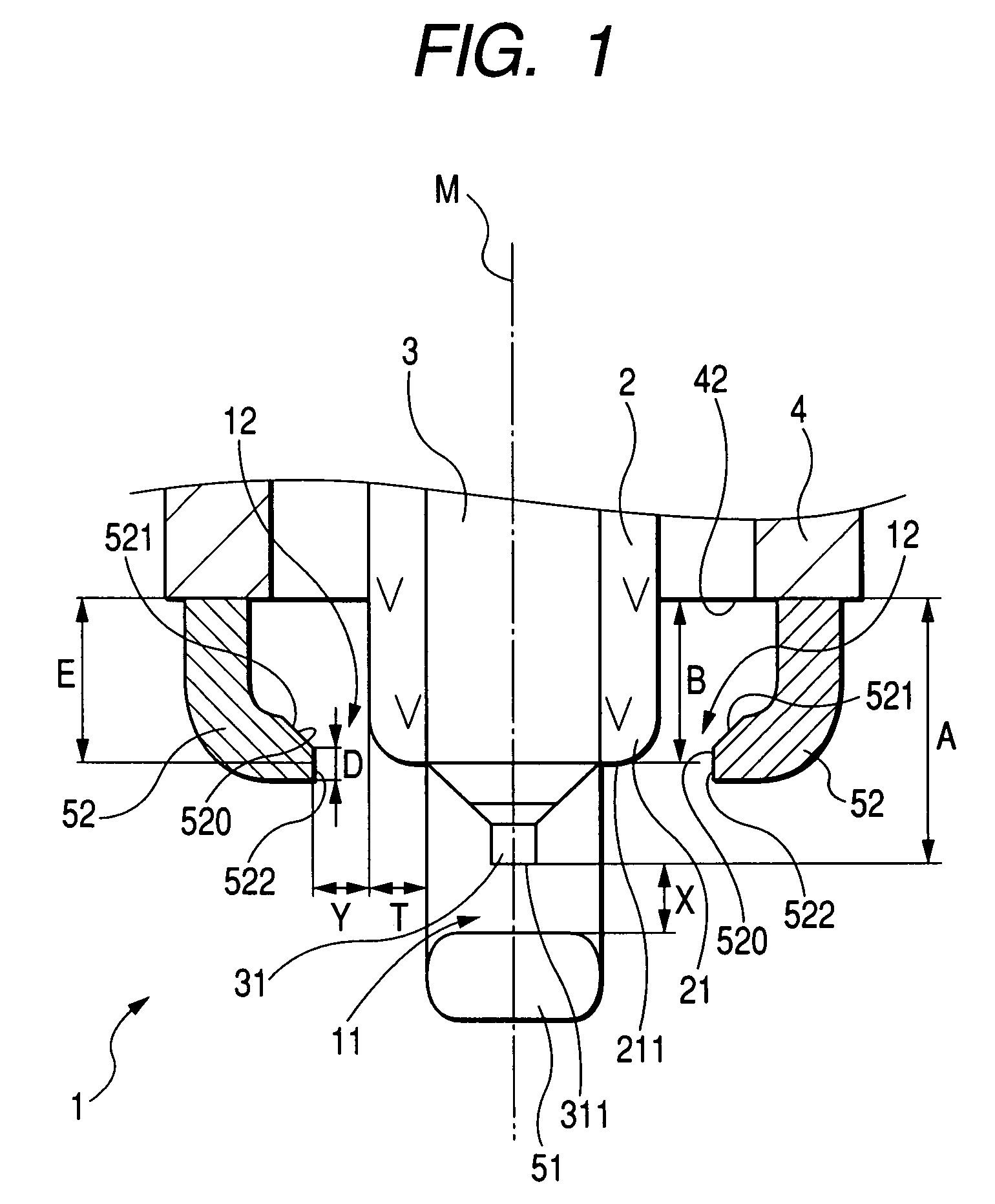
[0104]We performed tests to evaluate the carbon fouling resistance of the spark plug 1 in terms of the thickness T of the nose 21 of the porcelain insulator 2.

[0105]We prepared plug samples which were identical in structure with the spark plug 1 of FIG. 1 in that the auxiliary ground electrodes 52 have the increasing-radial distance surfaces 521 and had different values of 0.5 mm, 0.7 mm, 0.9 mm, and 11.0 mm in the wall thickness T of the insulator nose 21. We also prepared comparative plug samples which were identical in structure with the prior art spark plug 9, as illustrated in FIG. 22, in that the auxiliary ground electrodes 952 have no increasing-radial distance surfaces and 1.0 mm in the wall thickness T of the insulator nose 921.

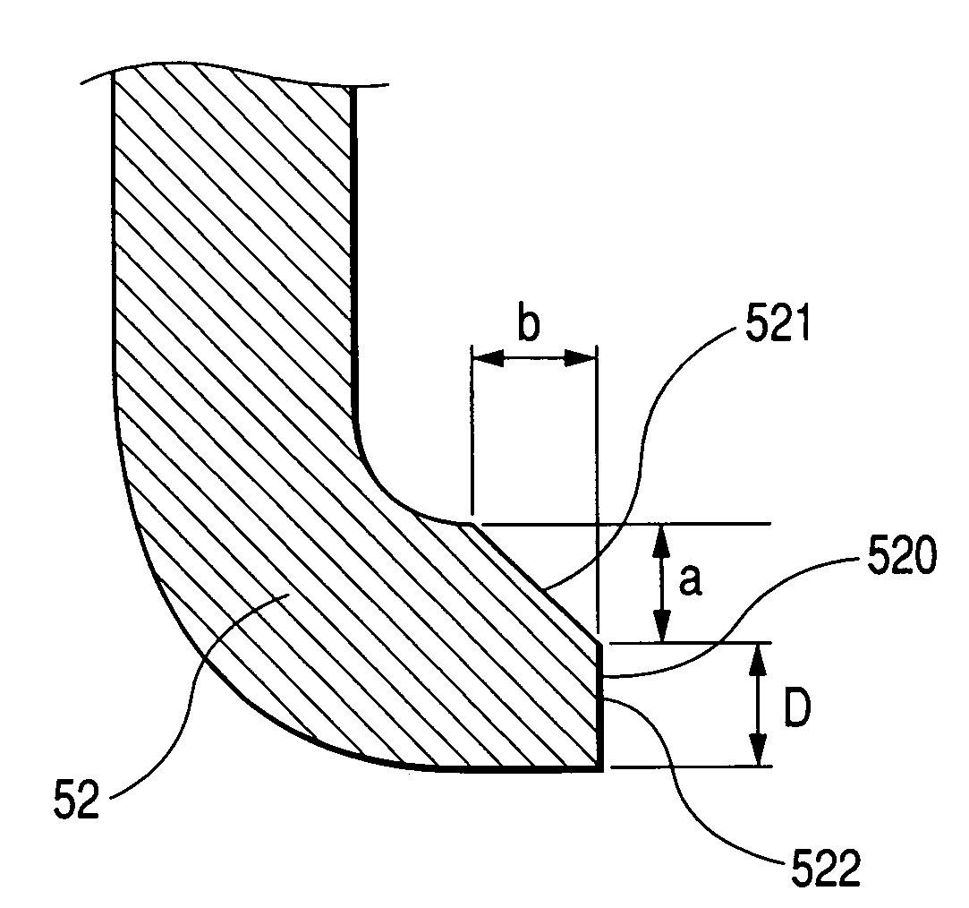
[0106]Each of the samples had the above described dimensions X=1.0 mm, Y=0.5 mm, A=4.5 mm, B=3.0 mm, E=2.8 mm, D=0.80 mm. The increasing-radial distance surface 521 was of a C-shape and had the widths a and b that were both 0.3 mm. However, in each o...

experiment 2

[0112]We also performed tests to evaluate the ignitability of fuel in the engine by sparks produced within the auxiliary spark gaps 12 in terms of a relation between the distance A between the top end 42 of the metal shell 4 and the tip end 311 of the center electrode 3 and the distance E between the top end 42 and the center of the constant-radial distance surface 522 of each of the auxiliary ground electrodes 52.

[0113]We prepared plug samples which were identical in structure with the spark plug 1 of FIG. 1 and in which A=4.5 mm, and B=E=3.0 mm, 2.0 mm, 1.5 mm, and 1.0 mm. Other dimensions were identical with those in the plug samples as used in the above first experiment.

[0114]The tests were conducted in conformity to low-temperature smoldering fouling test procedures, as specified by JIS D 1606. We observed the waveform of voltage of spark discharges in each sample using an oscilloscope and broken down the spark discharges into those produced in the main spark gap 11 and those p...

experiment 3

[0117]We performed tests to evaluate the carbon fouling resistance of the spark plug 1 in terms of a relation between the distance B between the top end 42 of the metal shell 4 and the top end 211 of the porcelain insulator 2 and the distance E between the top end 42 and the center of the constant-radial distance surface 522 of each of the auxiliary ground electrodes 52.

[0118]We prepared plug samples which were identical in structure with the spark plug 1 of FIG. 1 and had the same value of 4.5 m in the distance A, the same value of 3.0 mm in the distance B, and different values of 4.5 mm, 4.0 mm, 3.0 mm, 1.5 mm, and 1.0 mm in the distance E, respectively. Other dimensions were identical with those in the test samples used in the above first experiment.

[0119]We conducted the tests in conformity to the above described low-temperature smoldering fouling test procedures, as specified by JIS D 1606, and then observed the appearance of the insulator nose 21 (i.e., the degree to which car...


PUM


Abstract

A spark plug for an internal combustion engine is provided which includes a metal shell, a porcelain insulator, a center electrode, a main ground electrode, and auxiliary ground electrodes. Each of the auxiliary ground electrodes has an end face facing the insulator to define an auxiliary spark gap. The end face includes an increasing-radial distance surface which is located at a distance from a longitudinal center line of the spark plug in a radial direction thereof which increases as approaching to the metal shell. The insulator nose has a wall thickness T meeting a relation of 0.3 mm≦T≦0.7 mm. This avoids a great local increase in electrical field strength on the auxiliary ground electrode to minimize excessive discharge within the auxiliary spark gap to enhance carbon fouling resistance and durability of the spark plug.

Description

CROSS REFERENCE TO RELATED DOCUMENT[0001]The present application claims the benefits of Japanese Patent Application No. 2004-267097 filed on Sep. 14, 2004 and Japanese Patent Application No. 2005-136162 filed May 9, 2005, disclosures of which are totally incorporated herein by reference.BACKGROUND OF THE INVENTION[0002]1. Technical Field of the Invention[0003]The present invention relates generally to a spark plug with increased durability and carbon fouling resistance for internal combustion engines which may be used in automotive vehicles, co-generation systems, or gas feed pumps.[0004]2. Background Art[0005]Japanese Patent No. 3140006 (U.S. Pat. No. 6,229,253 B1) teaches a multi-ground electrode spark plug for internal combustion engines. FIG. 22 shows a multi-ground electrode spark plug 9 of the same type.[0006]The spark plug 9 includes a porcelain insulator 92, a center electrode 93 retained within the porcelain insulator 92, a metal shell 94 in which the porcelain insulator 92...

Claims


Application Information

Patent Timeline
Patent Type & Authority Patents(United States)
IPC IPC(8): H01T13/20H01T13/00H01T21/02
CPCH01T13/20H01T13/32
Inventor KOYAMA, TAIJIKANAO, KEIJI
Owner DENSO CORP
Why Eureka
Try Eureka